
What are the common errors in precision during the processing of micro parts
author: Hansheng Automation
2022-04-06
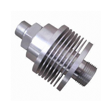
The common error problems in precision during the processing of micro parts include:
1. Machining principle error of micro parts
The machining principle error of micro parts refers to the error generated by using approximate blade contours or approximate transmission relationships for machining. Machining principle errors often occur in the machining of threads, gears, and complex surfaces.
For example, for the gear hob used to process the involute gear, in order to facilitate the manufacturing of the hob, Archimedes basic worm or normal straight profile basic worm is used instead of the involute basic worm, which causes errors in the involute tooth profile of the gear. For example, when turning modular worms, due to the fact that the pitch of the worm is equal to the circumferential pitch of the worm gear (i.e. m π), where m is the modulus and π is an irrational number, the number of teeth in the replacement gear of the lathe is limited. When selecting the replacement gear, π can only be reduced to an approximate fractional value (π=3.1415) for calculation, which will cause inaccurate tool response to the workpiece forming motion (spiral motion), resulting in pitch error.
In machining, approximate machining is generally used to improve productivity and economy, provided that the theoretical error can meet the machining accuracy requirements (i.e., 10% -15% dimensional tolerance).
2. Adjustment error
The adjustment error of a machine tool refers to the error caused by inaccurate adjustment.
3. Manufacturing errors and wear of fixtures
The error of fixtures mainly refers to:
(1) Manufacturing errors of positioning components, tool guide components, indexing mechanisms, clamp details, etc;
(2) The relative size error between the working surfaces of various components mentioned above after fixture assembly;
(3) Wear on the working surface of the fixture during use.
4. Machine tool error
Machine tool error refers to the manufacturing error, installation error, and wear of a machine tool. Mainly including guide error of machine tool guide rail, rotation error of machine tool spindle, and transmission error of machine tool transmission chain.
(1) Guide error of machine tool guide rail
1) Guide rail guidance accuracy - the degree to which the actual motion direction of the moving part of the guide rail pair matches the ideal motion direction.
Mainly including:
Straightness of guide rail in horizontal plane Δ Y and straightness in the vertical plane Δ Z (bending).
Parallelism (twisting) of the front and rear guide rails.
The parallelism or perpendicularity error between the guide rail and the spindle rotation axis in the horizontal and vertical planes.
2) The influence of guide rail guidance accuracy on cutting machining
Mainly considering the relative displacement between the tool and the workpiece in the error sensitive direction caused by guide rail error. When turning, the error sensitive direction is the horizontal direction, and the machining error caused by the guidance error in the vertical direction can be ignored; The error sensitive direction during boring processing changes with the rotation of the tool; During planing, the error sensitive direction is the vertical direction, and the straightness of the bed guide rail in the vertical plane causes surface straightness and flatness errors.
(2) Machine tool spindle rotation error
The spindle rotation error of a machine tool refers to the drift of the actual rotation axis from the ideal rotation axis. Mainly including spindle end face circular runout, spindle radial circular runout, and spindle geometric axis inclination swing.
1) The impact of spindle end face circular runout on machining accuracy:
No impact when machining cylindrical surfaces.
When turning or boring the end face, there will be perpendicularity error or flatness error between the end face and the cylindrical axis.
When machining threads, there will be pitch cycle errors.
2) The impact of radial runout of the spindle on machining accuracy:
If the radial rotation error is manifested as a simple harmonic linear motion of its actual axis in the y-axis coordinate direction, the hole drilled by the boring machine is an elliptical hole, and the roundness error is the radial circular runout amplitude; And the holes made by the lathe have little effect.
If the geometric axis of the spindle moves eccentrically, a circle with a radius equal to the distance from the tool tip to the average axis can be obtained for both turning and boring.
3) The influence of the tilt angle swing of the spindle geometric axis on machining accuracy:
A conical trajectory with a geometric axis at a certain cone angle relative to the average axis in space, viewed from each cross-section, is equivalent to an eccentric motion of the geometric axis around the average axis, while the eccentricity values vary from axis to axis.
The geometric axis oscillates in a certain plane, and from each cross-section, it is equivalent to the actual axis moving in a simple harmonic straight line in a plane, while from the axial direction, the amplitude of the oscillation varies from place to place.
In fact, the inclination swing of the geometric axis of the main axis is the superposition of the above two.
(3) Transmission error of machine tool transmission chain
The transmission error of the machine tool transmission chain refers to the relative motion error between the first and last transmission components in the transmission chain.
5. Process system deformation under force
The process system undergoes deformation under the effects of cutting force, clamping force, gravity, and inertia force, which disrupts the mutual positional relationship of the adjusted components of the process system, leading to machining errors and affecting the stability of the machining process. Mainly considering machine tool deformation, workpiece deformation, and total deformation of the process system.
(1) The influence of cutting force on machining accuracy
Only considering the deformation of the machine tool, for machining shaft parts, the force deformation of the machine tool causes the workpiece to be in a saddle shape with thick ends and thin middle, resulting in cylindricity error. Only considering the deformation of the workpiece, for machining shaft parts, the deformation of the workpiece under force causes the workpiece to form a drum shape with thin ends and thick middle after processing. For machining hole type parts, considering the deformation of the machine tool or workpiece separately, the shape of the workpiece after processing is opposite to that of the processed shaft type parts.
(2) The influence of clamping force on machining accuracy
When clamping the workpiece, due to the low stiffness of the workpiece or improper clamping force, the workpiece undergoes corresponding deformation, resulting in machining errors.
What are the five major benefits of using a five axis machining center in a five axis machining center factory
What is the process flow for processing automotive parts
Related Article

Let us go over the foundations of the electroplating procedure. Electroplating involves several phases, and from pre-treatment to post-treatment there are several really significant ones.
The basic principle of surface treatment of precision parts in CNC machining

Audio panels, electronic cigarette shells, nameplateLOG, watch shells, etc. are among the CNC processing of high surface texture needs components.
CNC machining aluminum alloy parts high-quality surface texture process explained in detail

Metallic finishing, sometimes known as metallic finishing, is the process of using several techniques to change the surface of an object in order to improve appearance and performance, such as corrosion resistance, discoloration resistance, chemical resistance, abrasion resistance, and hardness, modify electrical conductivity, remove burrs, or apply a specific color to a machined part.
Metal CNC finishing surface treatment process and its working principle
