
Tool Setting Method for Five Axis Machining Centers in Five Axis Machining Center Factory
author: Hansheng Automation
2022-04-22
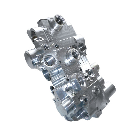
The five axis linkage machining center, also known as the five axis machining center, is a high-tech and high-precision machining center specifically used for machining complex surfaces. The machining center system has a significant impact on industries such as aviation, aerospace, military, scientific research, precision equipment, and high-precision medical equipment. So, is there a method for tool alignment in a five axis machining center? Let's follow the editor and take a look!
1. Analysis of coordinate relationship between machine tool and workpiece
The machine tool coordinate system, also known as the mechanical coordinate system, is set by the machine tool manufacturer to determine the position of the workpiece and tool in the machine tool. After startup, the machine tool usually automatically finds the origin of the machine coordinate system by returning to zero and returning to the reference point, which is the reference system for all other coordinate systems.
How to convert the workpiece coordinate system to the machine coordinate system is crucial for operators. By discussing the tool methods of CNC milling machines and machining centers, the base point coordinates in the workpiece coordinate system are converted into machine tool coordinate systems, and the relationship between the two coordinate systems is established. CNC milling machines or machining centers typically store six different workpiece parts; When cutting tools, the tool value can be input into any preset coordinate system, and the corresponding coordinate system can be input for machining to call up the offset amount in the memory.
2. Knife setting method
Due to the fact that the machining center involves the X axis, Y axis, and Z axis, there are three coordinate axes. Therefore, during the tool alignment process, it is necessary to align the X axis, Y axis, and Z axis separately (note that the three coordinate axes are not in any particular order during tool alignment). The trial cutting method is actually a widely used tool setting method.
3. Unilateral knife alignment method
The workpiece coordinate system is built in the middle of the blank, assuming that the blank size is 100X80X20, and all surfaces of the blank are processed, the selected tool size is φ 20. Because the projection of the tool is circular, it is based on the tool φ 20 circles are used as cutting tools. The Y-axis tool alignment requires completing the following steps:
One is to install the workpiece on the workbench through a fixture, and when clamping, the position of the knife should be left on all four sides of the workpiece.
The second is to rotate the tool at a certain speed, manually or manually move the workbench to make the tool close to the left side of the blank, move the spindle to make the tool at an appropriate depth in the Z direction, observe the iron filings or listen to the cutting sound to determine whether the tool is in contact with the left side of the blank, and enter the G54-G59 coordinate system interface through the OFSSET button on the control panel. G takes the 54 coordinate system as an example. Position the cursor to the corresponding cursor X, enter - (100/2+20/2)=-60, and then click on Measure. At this point, the X value is aligned with the tool. If the tool is close to the right side of the blank, the value that should be entered at this time is+60. Similarly, tool alignment in the Y-axis direction can be achieved by controlling the front and back contact of the tool with the blank.
4. Z-axis tool alignment
Tool rotation controls the rapid movement of the workbench and spindle, allowing the tool to move to a safe distance near the surface of the workpiece, reducing the movement speed and making the bottom of the tool come into contact with the surface of the workpiece. At this point, call up the coordinate system, position the cursor as Z input 0, and click the corresponding soft key below the measurement to achieve Z-axis tool alignment.
In this tool alignment method, for X-axis and Y-axis knives, the tool only needs to contact one side of the blank, but when aligning the tool, it is necessary to know the dimensions of the blank and the tool, so it is suitable for regular blank cutting tools.
How to determine the reasons for the decrease in accuracy during CNC machining
How to avoid accidents of tool collision in large CNC machining centers
Related Article

Let us go over the foundations of the electroplating procedure. Electroplating involves several phases, and from pre-treatment to post-treatment there are several really significant ones.
The basic principle of surface treatment of precision parts in CNC machining

Audio panels, electronic cigarette shells, nameplateLOG, watch shells, etc. are among the CNC processing of high surface texture needs components.
CNC machining aluminum alloy parts high-quality surface texture process explained in detail

Metallic finishing, sometimes known as metallic finishing, is the process of using several techniques to change the surface of an object in order to improve appearance and performance, such as corrosion resistance, discoloration resistance, chemical resistance, abrasion resistance, and hardness, modify electrical conductivity, remove burrs, or apply a specific color to a machined part.
Metal CNC finishing surface treatment process and its working principle
