
The harmonic reducer mainly consists of three basic components
author: Hansheng Automation
2023-05-10
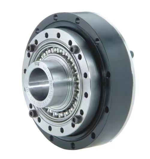
The harmonic reducer mainly consists of three basic components: (none of which are indispensable)
1. A rigid gear (rigid wheel) with an inner ring gear, which is equivalent to the central wheel in a planetary system;
2. A flexible gear (flexible gear) with an outer gear ring, which is equivalent to a planetary gear;
3. Wave generator, which is equivalent to a planetary carrier.
The use of harmonic reducers usually adopts the form of active wave generator, fixed rigid wheel, and flexible wheel output. Among them, rigid wheel: the number of teeth is slightly greater than that of flexible wheel; Flexible wheel: a thin-walled gear that can produce significant elastic deformation; Wave generator: H is a rod-shaped component, with rolling bearings at both ends forming rollers that press tightly against the inner wall of flexible wheel 1; The length of the wave generator is larger than the diameter of the undeformed inner circle of the flexible wheel: when the wave generator is installed into the inner circle of the flexible wheel, it forces the section of the flexible wheel to undergo elastic deformation from the original circle and become elliptical, causing the flexible wheel teeth near the two ends of its long axis to be inserted into the teeth groove of the rigid wheel, becoming fully engaged; And the gear teeth near the two ends of its short shaft are completely out of contact and in a detached state. The teeth of other sections on the circumference are in a transitional state of engagement and detachment. The process from engagement to disengagement is in a state of engagement or engagement. When the wave generator continuously rotates, it forces the flexible wheel to continuously deform, causing the teeth of the two wheels to engage, engage, disengage, and re engage, continuously changing their respective working states throughout the cycle, thus achieving slow rotation of the flexible wheel relative to the rigid wheel in the opposite direction of the wave generator H. The so-called staggered tooth motion was generated, thereby achieving the transmission of motion between the active wave generator and the flexible wheel. When working, the fixed rigid wheel is driven by the motor to rotate the wave generator, and the flexible wheel serves as the driven wheel to output and drive the load to move. During the transmission process, the number of cycles during which the wave generator rotates once and a certain point on the flexible wheel deforms is called the wave number, denoted by n. Commonly used are two waves and three waves.
The principle of wave accelerator transmission is the difference in the number of teeth between flexible gears and rigid gears.
Because the number of teeth is different, when the meshing point is rotated from 0 ° (where several teeth of the inner and outer teeth mesh together), the inner and outer teeth cannot be completely meshed. This can be referred to. Assuming that the number of teeth of the inner and outer teeth is exactly the same, when the wave generator rotates 90 ° to mesh the teeth at the 90 ° position, the positions of the teeth (inner and outer) that were originally meshed at 0 ° remain unchanged, but the number of teeth of the two gears is different, So the internal teeth at 0 ° will rotate in the opposite direction with the rotation of the wave generator.
The difference between the principle of a gearbox and a frequency converter
Main characteristics of harmonic reducer products
Related Article

Let us go over the foundations of the electroplating procedure. Electroplating involves several phases, and from pre-treatment to post-treatment there are several really significant ones.
The basic principle of surface treatment of precision parts in CNC machining

Audio panels, electronic cigarette shells, nameplateLOG, watch shells, etc. are among the CNC processing of high surface texture needs components.
CNC machining aluminum alloy parts high-quality surface texture process explained in detail

Metallic finishing, sometimes known as metallic finishing, is the process of using several techniques to change the surface of an object in order to improve appearance and performance, such as corrosion resistance, discoloration resistance, chemical resistance, abrasion resistance, and hardness, modify electrical conductivity, remove burrs, or apply a specific color to a machined part.
Metal CNC finishing surface treatment process and its working principle
