
How to Measure Roundness Error in Precision Parts Processing
author: Hansheng Automation
2023-05-16
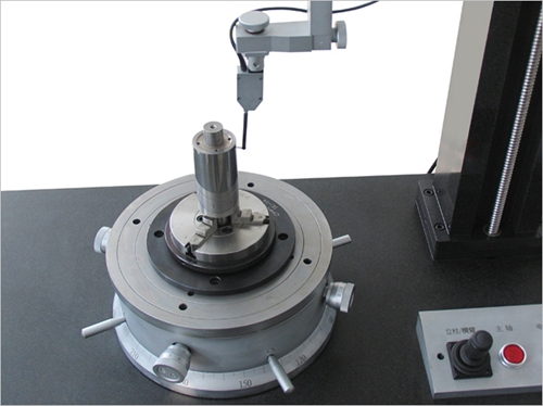
In the processing of precision parts, the roundness error can be checked using the roundness meter method and the two point and three point method. The principle of a roundness tester is to place the measured workpiece on the roundness tester workbench, align the rotation axis, and make the measuring head of the roundness tester come into contact with the outer circle of the workpiece and rotate. The measurement results are ultimately displayed through sensors, amplifiers, filters, and calculation circuits. If the output is an actual contour shape, a concentric circle template set can be used, with the difference in the radii of two concentric circles as the roundness error of a certain section. The roundness tester is suitable for measuring parts with high precision requirements.
Two point method and three point method can be used to measure roundness error when the shape of the measured contour is an even number of edges and circles. Using measuring instruments such as calipers, micrometers, and micrometers, measure the maximum difference in diameter along the entire circumference of a regular cross-section, and use half of it as the roundness error of that cross-section. The calculation formula is:
Due to the fact that the circles with the largest and smallest diameters are not necessarily concentric, this method is only an approximate measurement.
When the measured contour is an odd number of edges and circles, the roundness error cannot be measured using the two point method. In this case, the three point method can be used for measurement. Support the measured workpiece with a V-shaped frame, measure the maximum difference in rotation of the workpiece with an indicator, and take it as the roundness error of the cross-section. Commonly used V-frame angle α There are 60 °, 72 °, 90 °, 108 °, and 120 °. The three-point method can also be used for high-precision measurement in Precision Parts machining.
What are indexable milling cutters in precision parts processing
How to Mill Non circular Gears in Precision Parts Processing
Related Article

Let us go over the foundations of the electroplating procedure. Electroplating involves several phases, and from pre-treatment to post-treatment there are several really significant ones.
The basic principle of surface treatment of precision parts in CNC machining

Audio panels, electronic cigarette shells, nameplateLOG, watch shells, etc. are among the CNC processing of high surface texture needs components.
CNC machining aluminum alloy parts high-quality surface texture process explained in detail

Metallic finishing, sometimes known as metallic finishing, is the process of using several techniques to change the surface of an object in order to improve appearance and performance, such as corrosion resistance, discoloration resistance, chemical resistance, abrasion resistance, and hardness, modify electrical conductivity, remove burrs, or apply a specific color to a machined part.
Metal CNC finishing surface treatment process and its working principle
