
Analysis of the Design Program for Harmonic Reducers
author: Hansheng Automation
2023-05-09
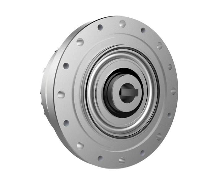
The following is the design procedure for a harmonic reducer
1. Design raw materials and data
1.1 The type, specification, speed, power (or torque), starting characteristics, short-term overload capacity, rotational inertia, etc. of the prime mover.
1.2 The type, specification, purpose, speed, power (or torque) of the working machinery. Working system: constant load or variable load, load diagram with variable load; Starting, braking, and short-term overload torque, starting frequency; Degree of impact and vibration; Direction of rotation, etc.
1.3 The connection method between the prime mover and the reducer, and whether there is radial and axial force on the shaft extension.
1.4 Installation type (relative position between reducer and prime mover, working machine, vertical, horizontal).
1.5 Transmission ratio and its allowable error.
1.6 Requirements for size and weight.
1.7 Requirements for service life, safety level, and reliability.
1.8 Environmental conditions such as temperature, dust concentration, airflow velocity, and pH; Lubrication and cooling conditions (whether there is circulating water, lubrication station), as well as limitations on vibration and noise.
1.9 Requirements for operation and control.
1.10 Source and inventory status of materials, blanks, and standard parts.
1.11 The manufacturing capacity of the manufacturing plant.
1.12 Requirements for batch size, cost, and price.
1.13 Delivery deadline.
The first four items mentioned above are necessary conditions, and other aspects can be designed according to conventional standards. For example, the design life is generally! When used in important occasions, the reliability should be relatively high.
2. Select the type and installation type of harmonic reducer
3. Preliminary determination of various process methods and parameters for harmonic reducer
Select the performance level, preliminarily determine the materials, heat treatment process, precision machining method, lubrication method, and lubricating oil for the gears and main components.
4. Determine the transmission stages of the harmonic reducer
Determine the number of transmission stages and transmission ratios at each level based on the total transmission ratio.
5. Initial geometric parameters
Preliminary calculation of gear transmission center distance (or pitch diameter), modulus, and other geometric parameters.
6. Overall scheme design
Determine the structure, shaft size, span, and bearing model of the reducer.
7. Verification
Verify the strength of load components such as gears, shafts, and keys, and calculate the bearing life.
8. Lubrication cooling calculation
9. Determine the accessories for the reducer
10. Determine the depth of gear carburization
If necessary, the calculation of process data such as tooth shape and tooth direction modification amount should also be carried out.
11. Draw construction drawings
Relevant national and industry standards should be implemented in the design.
The main factors that promote the improvement of the level of harmonic reducers
The difference between harmonic reducer and Rv reducer
Related Article

Let us go over the foundations of the electroplating procedure. Electroplating involves several phases, and from pre-treatment to post-treatment there are several really significant ones.
The basic principle of surface treatment of precision parts in CNC machining

Audio panels, electronic cigarette shells, nameplateLOG, watch shells, etc. are among the CNC processing of high surface texture needs components.
CNC machining aluminum alloy parts high-quality surface texture process explained in detail

Metallic finishing, sometimes known as metallic finishing, is the process of using several techniques to change the surface of an object in order to improve appearance and performance, such as corrosion resistance, discoloration resistance, chemical resistance, abrasion resistance, and hardness, modify electrical conductivity, remove burrs, or apply a specific color to a machined part.
Metal CNC finishing surface treatment process and its working principle
