
Analysis of Nine Major Reasons for "Dimensional Instability" of CNC Machining Machine Tools
author: Hansheng Automation
2022-11-14
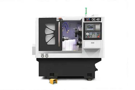
Analysis of Nine Major Reasons for "Dimensional Instability" of CNC Machining Machine Tools
1. CNC machining of workpieces with accurate dimensions and poor surface finish
Fault cause: The tool tip is damaged and not sharp. The machine tool resonates and is placed unevenly. The machine tool has crawling phenomenon. Poor processing technology.
Solution: If the tool wear is worn or damaged and is not sharp, regrind the tool or select a better tool to reset the tool. If the machine tool resonates or is placed unevenly, adjust the level, lay a foundation, and fix it smoothly.
The reason for mechanical crawling is severe wear on the guide rail of the carriage, wear or looseness of the screw ball. The machine tool should be maintained carefully, and the iron wire should be cleaned and lubricating oil should be added in a timely manner after commuting to reduce friction. Choose a coolant suitable for workpiece processing, and try to choose a higher spindle speed while meeting the processing requirements of other processes.
2. The workpiece produces a large and small taper phenomenon
Reason for malfunction: The machine tool was not placed properly, with one high and one low, resulting in unstable placement. When turning a long shaft, the contributing material is relatively hard, and the cutting tool has a deeper bite, resulting in the phenomenon of cutting over; The tailstock ejector pin is not concentric with the spindle.
The solution of Dongguan CNC machining factory is to use a level gauge to adjust the levelness of the machine tool, lay a solid foundation, and fix the machine tool to improve its toughness. Choose a reasonable process and appropriate cutting feed rate to avoid tool stress causing tool damage. Adjust the tailstock.
3. The phase light of the driver is normal, but the size of the processed workpiece varies from large to small
Fault cause: The machine tool carriage has been running at high speed for a long time, resulting in wear and tear on the screw and bearing; The repeated positioning accuracy of the tool holder may deviate during long-term use. The drag plate can accurately return to the processing starting point every time, but the size of the processed workpiece still changes. This phenomenon is generally caused by the spindle, and the high-speed rotation of the spindle causes severe bearing wear, resulting in changes in machining dimensions. Metal processing WeChat has good content and is worth paying attention to.
Solution: Use a dial gauge to lean against the bottom of the tool holder, while editing a fixed cycle program through the system to check the repeated positioning accuracy of the drag plate, adjust the screw clearance, and replace the bearing. Use a dial gauge to check the repeated positioning accuracy of the tool holder, adjust the machinery or replace the tool holder. Use a dial gauge to check if the workpiece is accurately returned to the starting point of the program after processing. If possible, repair the spindle and replace the bearings.
4. The size of the workpiece differs by a few millimeters from the actual size, or there is a significant change in a certain axis
Fault reason: The speed of rapid positioning is too fast, and the drive and motor cannot react. After long-term friction and wear, the mechanical drag screw and bearing are too tight and stuck. The tool holder is too loose and cannot be locked tightly after changing the tool. The editing program was incorrect and ended without any correspondence or cancellation of the knife repair. The electronic gear ratio or step angle of the system is set incorrectly.
Solution: If the fast positioning speed is too fast, adjust the speed of GO appropriately, increase or decrease the cutting speed and time to ensure that the driver and motor work normally at the rated operating frequency; If the drag plate and screw crane bearing are too tight and stuck due to machine tool wear, they must be readjusted and repaired.
If the tool holder is too loose after changing the tool, check whether the reverse time of the tool holder is met, whether the turbine worm inside the tool holder is worn, whether the gap is too large, and whether the installation is too loose; If it is caused by program reasons, it is necessary to modify the program, improve according to the requirements of the workpiece drawing, select a reasonable processing technology, and write the correct program according to the instructions in the manual. If the size deviation is found to be too large, check whether the system parameters are set reasonably, especially whether the electronic gear and step angle parameters are damaged. This phenomenon can be measured by using a dial indicator.
5. The processing effect of the arc is not ideal, and the size is not in place
Fault cause: The overlap of vibration frequencies leads to resonance. Processing technology. The parameter setting is unreasonable, and the feed speed is too high, causing the arc machining to be out of step. Loose or out of step caused by excessive clearance between screw rods or excessive tightening of screw rods. The Timing belt is worn.
Solution: Identify the components that generate resonance, change their frequency, and avoid resonance. Consider the processing technology of the workpiece material and develop a reasonable program. For stepper motors, the processing rate F cannot be set too high. Whether the machine tool is firmly installed and placed smoothly, whether the drag plate is too tight after wear, whether the gap increases or the tool holder is loose, etc. Replace the Timing belt. Metal processing WeChat has good content and is worth paying attention to.
6. Occasionally, workpieces exceeding the tolerance may occur in batch production
Reason for fault: The fixture must be carefully inspected, taking into account the operator's operating methods and the reliability of the fixture. Due to the size changes caused by the fixture, the fixture must be improved to prevent workers from making mistakes due to human negligence. The CNC system may be affected by fluctuations in external power sources or automatically generate interference pulses after interference, which can be transmitted to the driver, causing the driver to receive excess pulses and drive the motor away or less.
Solution: Understand and master its rules, and try to adopt some anti-interference measures.
For example, the strong electric cable with strong electric field interference is isolated from the signal line of the weak electric signal, and anti-interference absorption capacitors are added and shielded wires are used for isolation. In addition, check whether the ground wire is firmly connected and the grounding contact is nearest, and take all anti-interference measures to avoid system interference.
9. Unstable size changes caused by the system
Fault reason: The system parameter settings are not reasonable. The working voltage is unstable. The system is affected by external interference, resulting in system out of step. Capacitance has been added, but the impedance between the system and the driver does not match, resulting in the loss of useful signals; Abnormal signal transmission between the system and the driver; System damage or internal failure.
Solution: Whether the speed and acceleration time are too large, whether the spindle speed and cutting speed are reasonable, and whether the operator's parameter modifications have caused changes in system performance. Install voltage stabilizing equipment.
Ground the ground wire and ensure it is reliably connected, and add an anti-interference absorption capacitor at the pulse output contact of the driver. Choose the appropriate capacitor model. Check whether the signal connection line between the system and the driver is shielded, whether the connection is reliable, and whether the system pulse occurrence signal is lost or increased. Send the motherboard to the factory for repair or replacement.
Analysis of Adjustment Methods for Returning Reference Points of Small CNC Lathes in CNC Processing
How to solve the problem of surface accuracy and size control in precision parts machining
Related Article

Let us go over the foundations of the electroplating procedure. Electroplating involves several phases, and from pre-treatment to post-treatment there are several really significant ones.
The basic principle of surface treatment of precision parts in CNC machining

Audio panels, electronic cigarette shells, nameplateLOG, watch shells, etc. are among the CNC processing of high surface texture needs components.
CNC machining aluminum alloy parts high-quality surface texture process explained in detail

Metallic finishing, sometimes known as metallic finishing, is the process of using several techniques to change the surface of an object in order to improve appearance and performance, such as corrosion resistance, discoloration resistance, chemical resistance, abrasion resistance, and hardness, modify electrical conductivity, remove burrs, or apply a specific color to a machined part.
Metal CNC finishing surface treatment process and its working principle
