
What are the 4 types of gears
2025-08-31
What are the 4 types of gears? A Comprehensive Guide to Core Gear Designs
Gears are the backbone of mechanical transmission systems, converting rotational motion and torque between shafts to power everything from household appliances to industrial machinery. From the clock on your wall to the car you drive, gears enable precise control of speed, direction, and force. Yet for many people—whether hobbyists, students, or even new engineers—navigating the world of gear designs can be overwhelming. A fundamental question often arises: “What are the 4 types of gears?” These four primary gear categories—spur gears, helical gears, bevel gears, and worm gears—form the foundation of most mechanical systems, each tailored to solve specific transmission challenges. In this blog, we’ll break down each type in detail, exploring their unique structures, how they work, their strengths and weaknesses, and where you’ll find them in real-world applications. By the end, you’ll not only know the four core gear types but also understand why each is chosen for different tasks.
Spur Gears: The Simplest and Most Widely Used Gear Type
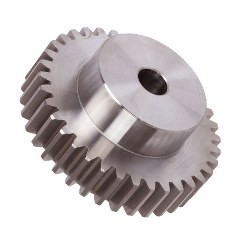
Spur gears are the most basic and common of the four gear types, recognized by their straight teeth and parallel shafts. Their simplicity in design and manufacturing makes them a go-to choice for countless low-to-medium speed applications. For anyone learning about gears, spur gears are often the starting point—and for good reason: they embody the fundamental principles of gear transmission.
Structure and Design
Spur gears feature straight teeth that run parallel to the gear’s central axis (the shaft it’s mounted on). The teeth are cut in a circular pattern around the gear’s circumference, with a uniform “module” (tooth size) and “pressure angle” (the angle of the tooth face, typically 20 degrees for standard applications). Most spur gears are cylindrical, with two key components: the “pitch circle” (the imaginary circle where teeth from two meshing gears make contact) and the “addendum/dedendum” (the height of the tooth above and below the pitch circle).
Spur gears are manufactured from a range of materials, depending on the application: plastic (for low-torque, quiet uses like toys), aluminum (for lightweight systems like small motors), and steel (for high-torque industrial machinery). Their design requires no complex machining—basic milling or hobbing (a gear-cutting process) is enough to produce accurate spur gears, keeping production costs low.
Working Principle
Spur gears operate on parallel shafts, with their teeth meshing directly along a line parallel to the shafts. When one spur gear (the “driver gear”) rotates, its teeth push against the teeth of a second spur gear (the “driven gear”), transferring motion and torque. The “gear ratio” (the ratio of the driven gear’s speed to the driver gear’s speed) is determined by the number of teeth on each gear: if a driver gear with 20 teeth meshes with a driven gear with 40 teeth, the driven gear will rotate at half the driver’s speed (a 2:1 reduction ratio).
A key characteristic of spur gear operation is “line contact”—the teeth make contact along a straight line, which creates instantaneous force transfer. While this ensures efficient power transmission (typically 95-98% efficiency), it also leads to higher impact and vibration compared to other gear types.
Advantages and Limitations
Spur gears’ main advantages stem from their simplicity:
- Low cost: Easy to manufacture with standard tools, making them ideal for budget-sensitive projects.
- High efficiency: Minimal energy loss during transmission, thanks to direct tooth contact.
- Simple installation: Parallel shafts require no complex alignment, reducing assembly time.
Their limitations, however, restrict their use in high-speed or high-precision systems:
- High noise and vibration: Line contact causes impact when teeth engage, leading to “gear whine” at speeds above 1,000 RPM.
- Limited torque capacity: The concentrated force on tooth lines can lead to tooth wear or breakage under heavy loads.
- No direction change: Spur gears only work on parallel shafts, so they can’t alter the direction of rotation.
Typical Applications
Spur gears are found in systems where simplicity and cost matter more than speed or quiet operation:
- Household appliances: Manual can openers, blenders (low-speed settings), and clock mechanisms.
- Toys and small devices: Toy cars, remote-controlled drones (basic models), and hand-cranked tools like egg beaters.
- Industrial machinery: Conveyor belts (low-speed), agricultural equipment (e.g., grain augers), and small electric motors (e.g., fan motors).
Helical Gears: Smoother Operation for High-Speed, High-Torque Systems
Helical gears build on the basic design of spur gears but add a critical improvement: angled teeth. This modification makes them quieter, more stable, and capable of handling higher speeds and torques—addressing the key limitations of spur gears. For applications like automotive transmissions or industrial motors, helical gears are the preferred choice.
Structure and Design
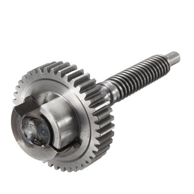
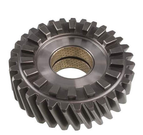
Unlike spur gears’ straight teeth, helical gear teeth are cut at an angle (called the “helix angle,” typically 15-30 degrees) relative to the gear’s axis. This angle creates a spiral pattern around the gear’s circumference, similar to the threads on a screw. Helical gears can operate on two types of shafts:
- Parallel shafts: The most common setup, where two helical gears mesh with opposite helix angles (one right-handed, one left-handed) to cancel out axial forces.
- Intersecting or 交错 shafts: In some cases, helical gears (called “crossed helical gears”) can mesh on non-parallel, non-intersecting shafts, though this is less common.
The angled teeth of helical gears increase the “contact ratio”—the number of teeth meshing at the same time. While spur gears typically have 1-2 teeth in contact, helical gears can have 2-4, distributing force more evenly across the teeth.
Working Principle
Helical gears transmit motion through “surface contact” rather than line contact. As the driver helical gear rotates, its angled teeth gradually engage with the driven gear’s teeth, creating a smooth, progressive meshing action. This gradual engagement eliminates the sudden impact of spur gears, reducing noise and vibration.
The helix angle also introduces an “axial force” (a force parallel to the shaft), which can cause the gear to push along the shaft. To counter this, helical gear systems use “thrust bearings” to stabilize the shafts and prevent movement. Despite this added complexity, the smooth operation of helical gears makes them ideal for high-speed applications (up to 10,000 RPM or more).
Advantages and Limitations
Helical gears’ key benefits make them superior to spur gears for demanding systems:
- Quiet, smooth operation: Gradual tooth engagement reduces noise and vibration, critical for automotive and industrial environments.
- Higher torque capacity: Increased contact ratio distributes force, allowing helical gears to handle heavier loads without wear.
- Suitable for high speeds: Minimal impact means helical gears perform reliably at high rotational speeds.
Their limitations are related to their design complexity:
- Axial force: Requires thrust bearings, adding cost and assembly complexity.
- Higher manufacturing costs: Cutting angled teeth requires specialized hobbing or grinding tools, making helical gears more expensive than spur gears.
- Lower efficiency at high helix angles: While still efficient (93-97%), efficiency drops slightly with larger helix angles due to increased sliding between teeth.
Typical Applications
Helical gears are used in systems where speed, torque, and quiet operation are priorities:
- Automotive transmissions: Manual and automatic gearboxes use helical gears to reduce noise and handle engine torque (e.g., a car’s 1st and 2nd gear pairs).
- Industrial machinery: Electric motors (high-speed), centrifugal pumps, and conveyor systems (heavy-duty).
- Precision equipment: CNC machine spindles (where vibration could ruin part accuracy) and robotics (smooth motion for arm joints).
Bevel Gears: Changing Direction with Intersecting Shafts
Unlike spur and helical gears (which work on parallel shafts), bevel gears are designed for intersecting shafts—their primary purpose is to change the direction of rotational motion. Whether you’re turning a steering wheel or using a hand drill, bevel gears are likely behind the direction shift.
Structure and Design
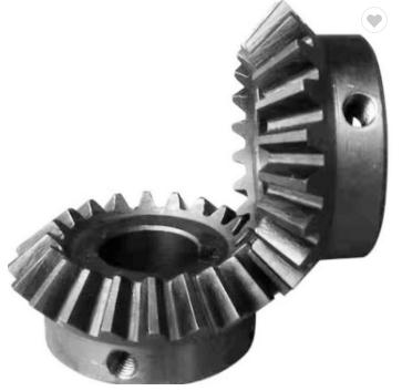
Bevel gears have a conical shape, with teeth cut into the cone’s surface. The shafts they connect intersect at a common point (called the “apex” of the cones), typically at a 90-degree angle (though other angles, like 45 degrees, are possible for specialized applications). The most common types of bevel gears include:
- Straight bevel gears: Teeth are straight and radiate from the apex, similar to spur gears but on a cone.
- Spiral bevel gears: Teeth are curved in a spiral pattern, like helical gears on a cone—offering smoother operation than straight bevel gears.
- Hypoid bevel gears: A variation where shafts are offset (not perfectly intersecting), allowing for larger gear ratios and used in automotive rear axles.
Bevel gears’ size is defined by their “cone distance” (the distance from the apex to the pitch circle) and “number of teeth,” with the gear ratio determined by the ratio of the driven gear’s cone diameter to the driver’s.
Working Principle
Bevel gears transmit motion by meshing their conical teeth at the point where the shafts intersect. For example, a straight bevel gear on a horizontal shaft (driver) will mesh with a bevel gear on a vertical shaft (driven), changing the direction of rotation by 90 degrees. The spiral design of spiral bevel gears adds gradual tooth engagement, similar to helical gears, resulting in quieter operation than straight bevel gears.
A key feature of bevel gears is their ability to adjust the gear ratio while changing direction. For instance, a small bevel gear (10 teeth) driving a large bevel gear (30 teeth) will reduce speed by 3:1 while rotating the driven shaft at a right angle.
Advantages and Limitations
Bevel gears’ unique design offers distinct advantages for direction change:
- Direction flexibility: Can change rotation direction by 90 degrees or more, critical for compact systems.
- Compact design: Conical shape allows bevel gears to fit in tight spaces (e.g., a car’s differential).
- Spiral variants for smoothness: Spiral bevel gears reduce noise and vibration, suitable for high-precision applications.
Their limitations are tied to their intersecting shaft requirement:
- Limited to intersecting shafts: Cannot be used for parallel or non-intersecting, non-parallel shafts.
- High manufacturing precision: Conical teeth require precise machining to ensure proper meshing—poor alignment leads to rapid wear.
- Lower torque than helical gears: Smaller contact ratio than helical gears means bevel gears handle less torque.
Typical Applications
Bevel gears are essential in systems that need to redirect rotational motion:
- Automotive systems: Car differentials (spiral bevel gears) redirect power from the driveshaft to the wheels, and steering systems use bevel gears to turn the front wheels.
- Hand tools: Cordless drills use bevel gears to change the direction of the motor’s rotation to the drill bit (forward/reverse).
- Industrial equipment: Machine tool spindles (to change the direction of cutting tools) and printing presses (to drive rollers at right angles).
Worm Gears: High Reduction Ratios with Self-Locking Capability
Worm gears are the most specialized of the four types, consisting of two components: a “worm” (a cylindrical shaft with a spiral thread, similar to a screw) and a “worm wheel” (a gear with teeth that mesh with the worm’s thread). Their defining feature is the ability to achieve extremely high gear ratios in a compact space—making them ideal for systems that need slow, powerful motion.
Structure and Design
The worm is the driver component, with a spiral thread cut around its circumference. The thread can be single-start (one continuous spiral) or multi-start (multiple parallel spirals), which affects the gear ratio. The worm wheel is a modified gear with teeth that are curved to match the worm’s thread—this “enveloping” design ensures maximum contact between the worm and wheel.
Worm gears operate on non-intersecting, non-parallel shafts (typically at a 90-degree angle). The gear ratio is calculated differently than other gears: for a single-start worm, the ratio is equal to the number of teeth on the worm wheel (e.g., a 40-tooth worm wheel with a single-start worm gives a 40:1 ratio). Multi-start worms increase the ratio proportionally (a 2-start worm with a 40-tooth wheel gives a 20:1 ratio).
Working Principle
When the worm rotates, its spiral thread engages with the worm wheel’s teeth, causing the wheel to rotate slowly. The worm’s thread acts like a ramp, gradually pushing the wheel’s teeth into motion—this creates a large reduction in speed while increasing torque. For example, a worm gear with a 50:1 ratio will turn the worm wheel once for every 50 rotations of the worm, multiplying torque by approximately 50 times (accounting for efficiency losses).
A critical feature of worm gears is “self-locking”: when the worm is the driver, it can turn the worm wheel, but the worm wheel cannot turn the worm. This is due to the high friction between the worm’s thread and the wheel’s teeth, which prevents reverse motion. Self-locking is essential for safety-critical applications (e.g., elevators), where the system must hold a load without power.
Advantages and Limitations
Worm gears’ unique capabilities make them irreplaceable for specific tasks:
- Extremely high gear ratios: Achieve ratios of 10:1 to 100:1 or more in a compact design, eliminating the need for multiple gear pairs.
- Self-locking safety: Prevents reverse motion, critical for lifting or holding loads.
- Quiet operation: The worm’s thread engages the wheel’s teeth gradually, resulting in low noise (even at high worm speeds).
Their limitations are related to friction and efficiency:
- Low efficiency: High friction between the worm and wheel leads to energy loss (efficiency ranges from 50-90%, depending on design).
- Heat generation: Friction causes heat buildup, requiring cooling systems for high-torque applications.
- Wear and tear: The worm (often made of hard steel) can wear down the worm wheel (typically made of softer bronze), requiring periodic replacement.
Typical Applications
Worm gears are used in systems that need high reduction ratios and safety:
- Lifting equipment: Elevators, cranes, and garage door openers use worm gears to lift heavy loads and prevent free fall.
- Automotive systems: Power steering systems use worm gears to convert the steering wheel’s rotation into linear motion for turning the wheels.
- Precision controls: Camera tripods (to adjust height smoothly), conveyor systems (slow, controlled movement), and medical equipment (e.g., hospital bed lifts).

FAQ
Which gear type is the simplest to manufacture, and why?
Spur gears are the simplest to manufacture. Their straight teeth run parallel to the gear’s axis, requiring only basic machining tools (like gear hobbing machines) to cut. Unlike helical gears (needing angled cuts) or bevel gears (needing conical shapes), spur gears have no complex geometry—this reduces production time and cost.
Why are helical gears quieter than spur gears during operation?
Helical gears have angled teeth that engage gradually with the driven gear’s teeth, creating surface contact rather than the line contact of spur gears. This gradual meshing eliminates the sudden impact of spur gear teeth slamming together, which is the main source of noise and vibration. The increased contact ratio (more teeth meshing at once) also distributes force evenly, further reducing noise.
What’s the primary purpose of bevel gears, and where are they commonly used?
The primary purpose of bevel gears is to change the direction of rotational motion between intersecting shafts (typically 90 degrees). They are common in automotive systems (e.g., car differentials, which redirect power from the driveshaft to the wheels) and hand tools (e.g., cordless drills, which change the motor’s rotation direction to the drill bit).
Do worm gears have a self-locking feature, and why is this important?
Yes, most worm gears are self-locking. This means the worm can turn the worm wheel, but the worm wheel cannot turn the worm—due to high friction between the worm’s spiral thread and the worm wheel’s teeth. Self-locking is critical for safety-critical applications like elevators, cranes, and garage door openers, as it prevents loads from falling or moving when power is cut off.
Which gear types are typically used in automotive transmissions, and why?
Automotive transmissions primarily use helical gears and spur gears (in some older models). Helical gears are preferred for most gears because they are quiet, smooth, and handle high torque—critical for reducing cabin noise and withstanding engine power. Spur gears may be used in low-speed, low-torque auxiliary systems (e.g., some manual transmission reverse gears, where noise is less of a concern). Bevel gears are also used in the differential to redirect power to the wheels.
References
- Gear Technology Magazine. (2025, March 15). The Four Core Gear Types: Design, Applications, and Performance Comparison. Retrieved from https://www.geartechnology.com/article/the-four-core-gear-types-design-applications-performance
- Mechanical Engineering Journal. (2024, November 8). Spur vs. Helical vs. Bevel vs. Worm Gears: Choosing the Right Design for Industrial Use. Retrieved from https://www.mechanicalengineeringjournal.com/article/gear-type-selection-industrial-applications
- Industrial Transmission Systems Report. (2025, January 22). Worm Gears: Self-Locking Mechanisms and Safety Applications in Heavy Machinery. Retrieved from https://www.industrialtransmissions.com/report/worm-gear-safety-applications-heavy-machinery
Which Industries Mostly Use CNC Machines
Related Article

CNC machines (Computer Numerical Control machines) have transformed manufacturing by delivering unmatched precision, repeatability, and efficiency across material types—from metals to plastics and composites.
Which Industries Mostly Use CNC Machines

CNC machining is celebrated for its precision and versatility in shaping metals, plastics, and composites—but its subtractive nature (removing material from a solid workpiece to create parts) raises a critical question: “Is CNC machining wasteful?” At first glance, the piles of metal shavings, plastic chips, and scrapped parts from CNC operations might suggest yes.
Is CNC machining wasteful

CNC machining and 3D printing are two pillars of modern manufacturing, each celebrated for its unique strengths—precision for CNC machining, design flexibility for 3D printing.
Is CNC faster than 3D printing
CNC machining has become a staple in metal fabrication, but not all metals respond equally to the process. For manufacturers, hobbyists, and beginners alike, the question “What is the easiest metal to CNC?” is critical—it directly impacts tool costs, production speed, and part quality.
What is the Easiest Metal to CNC