What is Gear Hobbing?
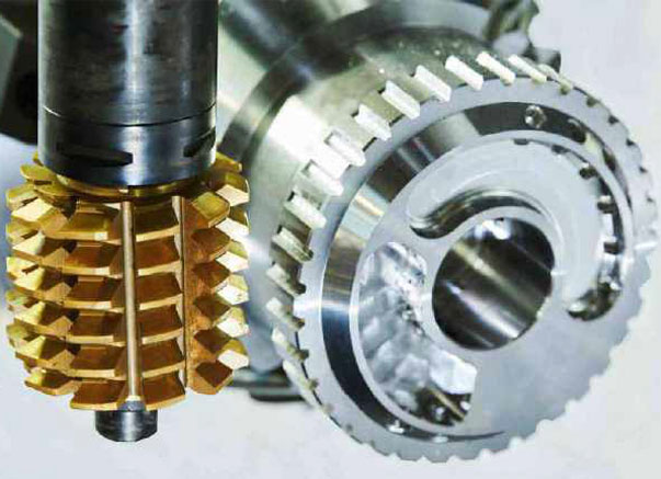
Hobbing is the process of cutting gear teeth into a workpiece using a hobbing machine. It is an efficient method of manufacturing high-precision, high-precision gears. The gear hobbing process involves a rotating workpiece and a rotating tool (called a hob) equipped with cutting edges. As the hob rotates and moves over the workpiece, it cuts its teeth into the surface, forming the desired gear shape. Gear hobbing services are vital to a range of industries including automotive, aerospace and heavy machinery. The manufacturing process produces gears that are durable, reliable, and able to withstand harsh operating conditions. Gears produced by the hobbing process meet the strictest quality and performance standards, ensuring they are suitable for demanding applications. Gear hobbing has several advantages, including the ability to produce gears with high precision, accuracy and consistency. This method enables the manufacture of gears in a wide variety of sizes, shapes and materials, making it an ideal solution for a wide variety of applications. Hobbing also produces gears with an excellent surface finish, minimizing the need for additional finishing processes, reducing manufacturing lead times and costs. When choosing a gear hobbing service provider, it is crucial to work with a company that has extensive experience in the machining industry, Hansheng Automation is not only a reputable gear hobbing service provider, but also can provide customized solutions to meet the needs of your project Unique needs.
What Is Gear Hobbing?
Hobbing is the process of cutting gears, cutting splines and cutting sprockets on a hobbing machine (a special type of milling machine). The gear teeth or splines gradually cut into the material (a flat cylindrical piece of metal) through a series of cuts made by a cutting tool called a hob. Hobbing is relatively fast and inexpensive compared to most other gear forming processes and is used in a wide variety of parts and quantities. Hobbing is especially common for machining spur and helical gears. A turning process similar to the hobbing process for external gears can be used to cut internal gears, where the internal gears are turned (rather than formed or broached) with rotating tools.
Gear hobbing uses a gear hobbing machine with two inclined axes. One spindle holds the workpiece blank and the other holds the hob. The angle between the main axis (axis) of the hob and the main axis of the workpiece depends on the type of part being manufactured. For example, when making spur gears, the spindle is kept at the hob lead angle, but when making helical gears, it is kept at the hob lead plus the helix angle of the helical gear. Gear hobbing includes straight, helical, straight helical, face, crown, worm, silicon and chamfer. The speeds of the two spindles maintain a constant ratio determined by the number of teeth cut into the blank. For example, a single-row hob with a gear ratio of 40:1 will rotate the hob 40 times for every revolution of the blank, forming 40 teeth on the blank. If the hob has multiple threads, multiply the speed ratio by the number of threads on the hob. The hob is then fed into the workpiece until the correct tooth depth is obtained. To do this, the hob is fed into the workpiece parallel to the axis of rotation of the blank. In mass production, multiple blanks are usually stacked and cut in one operation using appropriate fixtures. For very large gears, blanks can be pre-scored. Rough shape increases gear hobbing efficiency.
The process of hobbing tooth profile formation
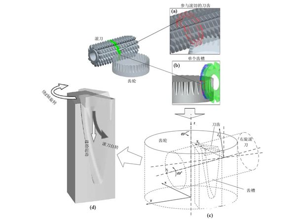
The formation method of gear hobbing tooth profile is shown in the figure. Starting from the contact cutting between the hob and the workpiece, the number of teeth involved in cutting gradually increases, and no longer increases after reaching a certain level. When the cutting is about to end, the cutter teeth participating in the cutting gradually decrease until the processing ends.
In order to objectively reflect the cutting conditions of all the cutting teeth in the cutting area, it is assumed that the gear has formed a complete tooth profile on the end face to analyze the cutting state of the hob when it continues to feed axially. According to this assumption, the initial position of the hob is at 0 position, the workpiece rotates one circle, and the hob feeds along the axis of the workpiece. At this time, part of the metal of ABC is cut in the tooth groove, and the complete tooth profile is formed on the end face of the gear. The workpiece turns around again, the center of the hob reaches position 2, and the metal in the same section as ABC is cut off in the tooth groove, so that the hob gradually cuts off all the metal in the tooth groove in the downward feed .
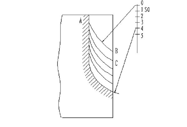
Alveolar cutting and tooth profile forming process
In the actual hobbing process, the processing of the tooth space to be processed does not start from the No. 0 cutter tooth in the creation center, but from the bN No. cutter tooth, as shown in the figure below. The position where the hob rotates counterclockwise around the gear blank by ϕ angle is the initial state where the bN number cutter tooth starts cutting the tooth groove to be processed.
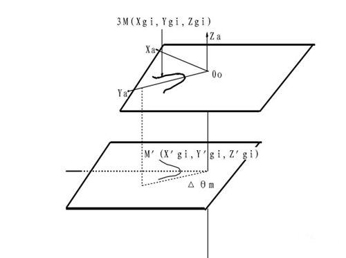
The process of gear hobbing is actually the process of meshing (creating) the helical surface of the hob with the tooth surface of the gear.
Gear hobbing belongs to multi-edge intermittent non-free bevel cutting. Compared with ordinary turning, the relative position and relative motion relationship between the cutter teeth and the workpiece are more complicated during the processing. During the hobbing process, each cutter tooth enters the cutting process. The shape of the formed alveolar corresponding to the state is different, the shape of the removed material is different, and the new alveolar entity formed is also different.
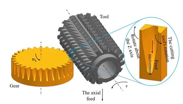
During the gear hobbing process, the gear workpiece rotates around the gear axis, while the hob rotates around its own axis and moves linearly along the gear axis (the principle of hobbing is shown in the figure below), so each tooth on the hob corresponds to its cutting The alveolar has a relative spatial position and motion relationship.
When hobbing, the hobbing machine must have the following movements:
1. Cutting motion (main motion) is the rotary motion of the hob, and its cutting speed is determined by the transmission ratio of the transmission gear.
2. Split-tooth movement is the rotational movement of the workpiece, and its movement speed must maintain the meshing relationship between the gear and the rack with the rotational speed of the hob. Its kinematic relationship is realized by the transmission ratio of the split tooth hanging wheel. For the single-line hob, when the hob rotates once, the gear blank needs to rotate through the indexing angle of one tooth, that is, 1/z revolution (z is the number of teeth of the gear to be processed).
3. The vertical feed movement is the vertical movement of the hob from top to bottom along the axis of the workpiece. This is the movement necessary to ensure that the entire tooth width is cut. The transmission ratio of the feed hanging wheel is passed through the screw rod connected to the hob holder. nuts to achieve.
When hobbing, the moving direction of the hob teeth must be consistent with the tooth direction of the cut gear. However, since the hob teeth are arranged on a helical line, the direction of the hob teeth is not perpendicular to the axis of the hob. Therefore, the tool holder must be turned at an angle to coordinate with the tooth direction of the gear. When hobbing spur gears, the turning angle is the helix angle of the hob. When hobbing the helical gear, the size and direction of the turning angle should be determined according to the helical direction of the helical gear and the size of the helix angle.
The gear hob is a special tool, each hob can process various spur or helical involute external cylindrical gears of different sizes with the same module but different numbers of teeth.
What is Cylindrical grinding?
What is CNC turning?