
What Is a Pinion Gear
2025-06-26
What Is a Pinion Gear?
In the intricate world of mechanical engineering, the pinion gear stands as a fundamental component in gear systems, enabling the transfer of motion and power between shafts. Whether in a car’s transmission, industrial machinery, or a simple household device, pinion gears play a critical role in converting speed and torque. This detailed blog post will explore the definition, design principles, applications, and key differences of pinion gears, providing a complete understanding for engineers, students, and mechanical enthusiasts.
What Is a Pinion Gear? Core Definition and Mechanics
Basic Definition
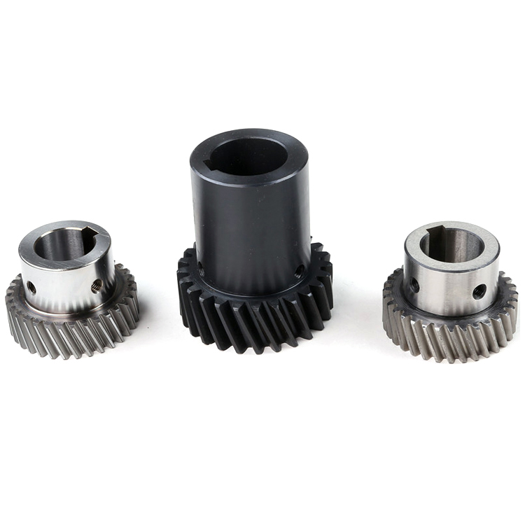
A pinion gear is a small-diameter gear with a relatively small number of teeth that meshes with a larger counterpart, known as a gear or bull gear. The term "pinion" specifically refers to the smaller gear in a gear pair, regardless of the gear type (spur, helical, bevel, or worm). Its primary role is to transmit rotational motion to the larger gear, often reducing speed while increasing torque (or vice versa, depending on the direction of power flow).
Key Characteristics
- Size Proportionality: Always paired with a larger gear; the size difference determines the gear ratio.
- Tooth Count: Fewer teeth than its mating gear, leading to a higher rotational speed when driving the larger gear.
- Shaft Interaction: Typically mounted on the input shaft (driving the system) or output shaft (being driven), depending on the desired speed-torque relationship.
Gear Ratio Relationship
The gear ratio between a pinion and its mating gear is calculated as:
Gear Ratio (GR) = Number of Teeth on Mating Gear (N₂) ÷ Number of Teeth on Pinion (N₁)
- A pinion with 20 teeth meshing with a 60-tooth gear results in a 3:1 ratio, reducing speed by 1/3 while tripling torque.
Pinion Gear vs. Other Gear Types: Key Differences
1. Pinion Gear vs. Spur Gear
- Spur Gear: A general term for any gear with straight teeth parallel to the shaft; a pinion can be a spur gear if it’s the smaller member in a spur gear pair.
- Key Distinction: "Pinion" refers to size relative to its mate, while "spur gear" describes tooth geometry. A spur gear can act as a pinion when paired with a larger spur gear.
2. Pinion in Bevel Gear Systems
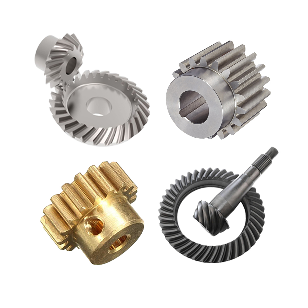
- In bevel gear pairs (connecting intersecting shafts), the smaller cone-shaped gear is called the pinion, meshing with a larger bevel gear.
- Example: In car differentials, the pinion gear drives the ring gear at a 90° angle, transmitting power to the wheels.
3. Pinion in Worm Gear Systems
- In worm gear sets, the worm (screw-like component) acts as the pinion, meshing with the worm wheel (larger gear).
- Here, the pinion (worm) typically has 1-4 threads, creating extremely high gear ratios (e.g., 50:1) for speed reduction.
Design and Mechanical Considerations
1. Key Design Parameters
- Number of Teeth (N₁): Determines the gear ratio and rotational speed; fewer teeth increase speed but reduce torque capacity.
- Module (m) or Diametral Pitch (DP): Defines tooth size and spacing, critical for meshing compatibility with the mating gear.
- Pressure Angle: Typically 20° or 25°, affecting load distribution and backlash; a larger angle improves load capacity but increases friction.
- Face Width: The width of the teeth along the gear’s axis, influencing contact area and load-bearing capability.
2. Material Selection
- Steels: Carbon steel (e.g., 1045) for general use; alloy steel (e.g., 4140) for high-torque applications (heat-treated for hardness).
- Non-Metallic Materials: Nylon or polycarbonate for low-load, quiet operation (e.g., in consumer electronics).
- Surface Treatments: Carburizing, nitriding, or induction hardening to enhance wear resistance and tooth strength.
3. Manufacturing Methods
- Hobbing: Most common for spur and helical pinions, using a hob tool to cut teeth efficiently.
- Milling: Used for low-volume production or complex geometries (e.g., bevel pinions).
- 3D Printing: Emerging for prototyping or custom pinions with non-standard materials.
Common Applications of Pinion Gears
1. Automotive Systems
Transmission and Differentials
- Manual Transmissions: The pinion gear meshes with layshaft gears to achieve different speed ratios, enabling acceleration and deceleration.
- Differentials: The pinion gear drives the ring gear, distributing power to the wheels while allowing speed differences during turns.
Power Steering
- Electric power steering systems use a pinion gear meshing with a rack to convert motor rotation into linear motion, assisting with steering effort.
2. Industrial Machinery
Gearboxes and Speed Reducers
- Pinion gears are integral in single-stage or multi-stage gearboxes, reducing motor speed to provide high torque for conveyor belts, pumps, and industrial robots.
Printing and Packaging Equipment
- Precision pinion gears ensure synchronized motion in paper feed systems and labeling machines, requiring tight tolerance for alignment and backlash.
3. Aerospace and Defense
Aircraft Actuation Systems
- Pinion gears in flap/slat mechanisms and landing gear drives transmit precise motion, often paired with bevel or planetary gears for compact, high-reliability solutions.
Missile Guidance Systems
- Miniature pinion gears in servo mechanisms control antenna rotation and flight control surfaces, demanding lightweight materials and high durability.
4. Consumer Electronics and Appliances
Robotics and Drones
- Small plastic pinion gears in gearboxes reduce motor speed for robotic arm movements or drone propeller control, balancing speed and precision.
Home Appliances
- Washing machines and dishwashers use pinion gears to transfer motor motion to drum drives, while garage door openers rely on pinions for smooth, low-noise operation.
Advantages and Limitations of Pinion Gears
Advantages
- High Speed Capability: As the smaller gear, pinions can operate at higher RPMs without excessive centrifugal stress.
- Compact Design: Enables large gear ratios in a small space, especially when paired with much larger mating gears.
- Versatility: Works with various gear types (spur, helical, bevel), adapting to parallel, intersecting, or offset shaft configurations.
Limitations
- Wear and Tear: The smaller teeth are more susceptible to surface wear, especially in high-load or poorly lubricated systems.
- Axial Thrust in Helical/Bevel Types: Helical and bevel pinions generate axial forces, requiring thrust bearings to manage lateral loads.
- Backlash Concerns: Clearance between teeth can cause positional inaccuracies in precision applications, requiring anti-backlash designs.
Design Best Practices for Pinion Gears
1. Tooth Strength Calculations
- Use the Lewis equation to determine bending stress on pinion teeth, ensuring they can withstand applied loads without fracture.
- Surface durability calculations (Hertz contact stress) prevent pitting and wear from repeated meshing.
2. Lubrication Strategies
- Grease lubrication for low-speed, enclosed systems (e.g., household appliances).
- Oil bath or spray lubrication for high-speed, high-load applications (e.g., automotive transmissions) to reduce friction and heat.
3. Backlash Control
- Pre-loaded gear pairs or adjustable center distances to minimize backlash in precision systems like CNC machines or robotics.
Case Study: Pinion Gear in a Wind Turbine Yaw System
- Application: A yaw drive system rotates the turbine nacelle to face the wind, using a pinion gear meshing with a large ring gear mounted on the tower.
- Design Parameters:
-
- Pinion: 20-tooth helical gear (steel, heat-treated)
-
- Ring Gear: 200-tooth cast iron gear
-
- Gear Ratio: 10:1 (reduces motor speed for precise yaw control)
- Advantages: Compact helical design minimizes noise, while the high ratio ensures stable positioning even in strong winds.
Conclusion: The Essential Role of Pinion Gears in Mechanical Systems
Pinion gears are far more than just "small gears"—they are the catalysts that enable mechanical systems to transform raw motion into usable power. From the high-torque demands of industrial machinery to the precision requirements of robotics, their ability to pair with larger gears to achieve specific speed-torque relationships makes them indispensable.
Understanding the design principles, material choices, and application nuances of pinion gears empowers engineers to optimize performance, durability, and efficiency in any mechanical system. As technology advances—from electric vehicles to renewable energy solutions—pinion gears will continue to evolve, adapting to new challenges while remaining a cornerstone of gear-driven innovation.
Whether you’re designing a new transmission, troubleshooting a manufacturing line, or simply curious about how machines work, the pinion gear’s role in mechanical motion is a testament to the elegance of engineering: small components with big responsibilities, driving progress one rotation at a time.
Do Electric Cars Have Gears
How to Calculate Gear Ratio
Related Article

Gears are the backbone of mechanical transmission systems, converting rotational motion and torque between shafts to power everything from household appliances to industrial machinery.
What are the 4 types of gears

CNC machines (Computer Numerical Control machines) have transformed manufacturing by delivering unmatched precision, repeatability, and efficiency across material types—from metals to plastics and composites.
Which Industries Mostly Use CNC Machines

CNC machining is celebrated for its precision and versatility in shaping metals, plastics, and composites—but its subtractive nature (removing material from a solid workpiece to create parts) raises a critical question: “Is CNC machining wasteful?” At first glance, the piles of metal shavings, plastic chips, and scrapped parts from CNC operations might suggest yes.
Is CNC machining wasteful
