
What is a Worm and Wheel Gear
2025-06-19
What is a Worm and Wheel Gear?
In the intricate domain of mechanical engineering, gear systems are fundamental components that enable the efficient transmission of motion and power. Among these, the worm and wheel gear, also known as the worm gear, stands out for its unique design and specialized functionality. This blog post will embark on a detailed exploration of what a worm and wheel gear is, delving into its structure, working principles, types, advantages, applications, and limitations, ensuring a comprehensive understanding of this essential mechanical element.
Defining the Worm and Wheel Gear
Basic Concept
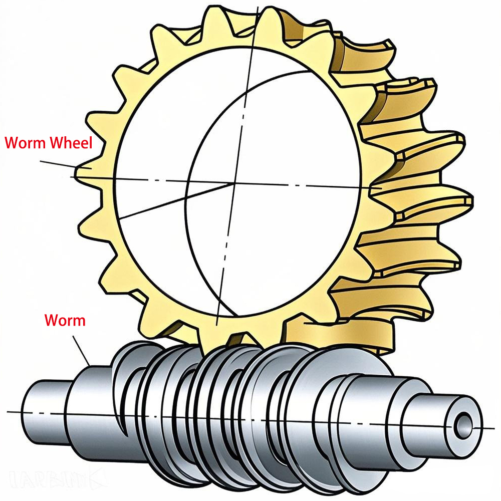
A worm and wheel gear is a gear arrangement that consists of two main components: the worm and the worm wheel (also called the gear or the 蜗轮). The worm resembles a screw, with a helical thread that wraps around its cylindrical body. The worm wheel, on the other hand, is a gear with teeth that are shaped to mesh with the worm's thread. This gear system is primarily used to transmit motion and power between two non - intersecting, perpendicular shafts, making it highly effective for applications where a significant speed reduction and torque increase are required.
Historical Significance
The concept of worm and wheel gears has a long - standing history, dating back to ancient civilizations. Early versions were used in various mechanical devices, such as water - lifting machines and clockwork mechanisms. Over time, with advancements in manufacturing techniques and materials, worm and wheel gears have evolved into more precise, efficient, and reliable components, playing a crucial role in modern - day industrial, automotive, and consumer applications.

Structure of the Worm and Wheel Gear
The Worm
The worm is the driving component in the worm and wheel gear system. Its design is similar to that of a screw, with a single or multiple threads (also known as starts). A single - start worm has one continuous thread, while a multi - start worm, such as a double - start or triple - start worm, has two or three separate threads, respectively. The number of starts on the worm affects the gear ratio and the speed of the worm wheel. A worm with more starts will result in a lower gear ratio and a faster - rotating worm wheel compared to a single - start worm, all else being equal.
The worm is typically made from materials with high strength and wear resistance, such as hardened steel. The surface of the worm is often precision - ground or rolled to ensure smooth meshing with the worm wheel and minimize friction and wear during operation.
The Worm Wheel
The worm wheel is the driven component. It has teeth that are cut in a way that they conform to the shape of the worm's thread. The teeth of the worm wheel are usually wider at the outer diameter and gradually taper towards the center to ensure proper meshing with the worm. The worm wheel is often made from materials with good anti - friction properties, such as bronze or brass, to reduce wear and improve the lifespan of the gear system. In some cases, composite materials or plastics may also be used for the worm wheel, especially in applications where weight reduction, noise reduction, or chemical resistance is a priduction, or chemical resistance is a priority.
The diameter of the worm wheel and the number of its teeth also play a significant role in determining the gear ratio of the worm and wheel gear system. A larger - diameter worm wheel with more teeth will result in a higher gear ratio, providing greater speed reduction and torque multiplication.
Working Principles of the Worm and Wheel Gear
Motion Transmission
The operation of a worm and wheel gear is based on the meshing of the worm's thread with the teeth of the worm wheel. When the worm rotates, its helical thread engages with the teeth of the worm wheel, causing the worm wheel to rotate in a perpendicular direction. The worm acts as a screw, and as it turns, it “drives” the worm wheel, similar to how a screw can move an object when turned.
The direction of rotation of the worm wheel depends on the direction of rotation of the worm and the hand (left - hand or right - hand) of the worm's thread. For example, a right - hand - threaded worm rotating clockwise will cause the worm wheel to rotate in a specific direction, while reversing the rotation of the worm or changing the hand of the thread will reverse the direction of the worm wheel's rotation.
Gear Ratio and Torque Conversion
One of the key features of a worm and wheel gear is its ability to provide a high gear ratio in a relatively compact space. The gear ratio is determined by the number of teeth on the worm wheel and the number of starts on the worm. For instance, if a worm has a single start and the worm wheel has 40 teeth, the gear ratio will be 40:1. This means that for every one revolution of the worm, the worm wheel will rotate only 1/40th of a revolution.
This high gear ratio results in a significant reduction in speed but a corresponding increase in torque. In other words, the worm and wheel gear can take a high - speed, low - torque input from the worm and convert it into a low - speed, high - torque output at the worm wheel. This characteristic makes worm and wheel gears ideal for applications where large amounts of torque are required to drive heavy loads, such as in lifting mechanisms, conveyor systems, and industrial machinery.
Types of Worm and Wheel Gears
Cylindrical Worm Gears
Cylindrical worm gears are the most common type. In this configuration, the worm has a cylindrical shape, and its thread wraps around the cylinder. The worm wheel meshes with the worm in a straightforward manner, and the two components are relatively easy to manufacture and assemble. Cylindrical worm gears are widely used in a variety of applications due to their simplicity, reliability, and cost - effectiveness.
Double - Enveloping Worm Gears
Double - enveloping worm gears have a more complex design. Both the worm and the worm wheel are shaped in a way that they envelop each other, providing a larger contact area between the meshing surfaces. This increased contact area results in a higher load - carrying capacity, better efficiency, and reduced wear compared to cylindrical worm gears. Double - enveloping worm gears are typically used in applications where high precision, heavy loads, and continuous operation are required, such as in large - scale industrial gearboxes and heavy - duty machinery.
Advantages of Worm and Wheel Gears
High Gear Ratio in a Compact Space
As mentioned earlier, worm and wheel gears can achieve a high gear ratio with a relatively small physical footprint. This makes them suitable for applications where space is limited but a significant speed reduction and torque increase are necessary. For example, in a small - scale robotic arm, a worm and wheel gear can be used to provide the required torque to move the arm's joints while fitting within the compact structure of the robot.
Self - Locking Capability
Many worm and wheel gear systems have a self - locking property. This means that once the worm wheel is in a stationary position, the worm cannot be back - driven by the load on the worm wheel. This self - locking feature is extremely useful in applications such as hoists and lifts, where it ensures the safety of the system by preventing the load from accidentally descending when the power is turned off or in case of a failure.
Smooth and Quiet Operation
The meshing of the worm's thread with the worm wheel's teeth occurs gradually, resulting in smooth motion transmission. This smooth engagement reduces vibrations and noise, making worm and wheel gears suitable for applications where quiet operation is required, such as in office equipment, medical devices, and some consumer appliances.
Applications of Worm and Wheel Gears
Industrial Machinery
In the industrial sector, worm and wheel gears are used in a wide range of machinery. They are found in conveyor systems, where they help to drive the belts or chains that transport materials. In manufacturing equipment, such as lathes, milling machines, and presses, worm and wheel gears are used to control the movement of various components, providing the necessary torque and precision. Additionally, they are used in industrial mixers, crushers, and other processing equipment to transfer power and ensure smooth operation.
Automotive Industry
Although less common than other gear types in automotive drivetrains, worm and wheel gears are still used in some specific applications. For example, they are used in the steering systems of some vehicles, where the high gear ratio of the worm and wheel gear helps to provide the necessary force to turn the wheels while also offering a self - locking feature for safety. Worm and wheel gears are also used in certain automotive accessories, such as power windows and sunroof mechanisms, to convert the rotational motion of the motor into the linear motion required to open and close these components.
Consumer Electronics
In consumer electronics, worm and wheel gears are used in devices where precise and quiet motion control is needed. For instance, in some high - end cameras, worm and wheel gears are used to control the zoom and focus mechanisms, ensuring smooth and accurate adjustments. They are also used in robotic vacuum cleaners to drive the wheels and control the movement of the cleaning head, providing the necessary torque to navigate different surfaces.
Limitations of Worm and Wheel Gears
Lower Efficiency
Compared to some other types of gear systems, such as spur gears or helical gears, worm and wheel gears generally have lower efficiency. The sliding contact between the worm's thread and the worm wheel's teeth generates more friction, resulting in energy losses in the form of heat. This lower efficiency can be a drawback in applications where energy conservation is a priority.
Higher Wear and Maintenance
Due to the sliding contact and the high loads involved, worm and wheel gears are prone to wear over time. The worm, in particular, can experience significant wear, especially if the gear system is not properly lubricated or maintained. Regular lubrication is essential to reduce friction and wear, and periodic inspection and replacement of worn - out components may be required, increasing the maintenance costs and downtime of the system.
The worm and wheel gear is a remarkable mechanical component with a unique design and a wide range of applications. Its ability to provide high gear ratios, self - locking functionality, and smooth operation makes it indispensable in many industries. However, it also has its limitations, such as lower efficiency and higher wear. As technology continues to advance, ongoing research and development efforts aim to improve the performance, efficiency, and durability of worm and wheel gears, further expanding their potential applications in the future. Whether you are an engineer, a designer, or simply interested in the fascinating world of mechanical engineering, understanding the worm and wheel gear is key to appreciating the complexity and ingenuity of modern - day machinery.
What Are Worm and Wheel Gears Used For
What is a Helical Gear
Related Article

Gears are the backbone of mechanical transmission systems, converting rotational motion and torque between shafts to power everything from household appliances to industrial machinery.
What are the 4 types of gears

CNC machines (Computer Numerical Control machines) have transformed manufacturing by delivering unmatched precision, repeatability, and efficiency across material types—from metals to plastics and composites.
Which Industries Mostly Use CNC Machines

CNC machining is celebrated for its precision and versatility in shaping metals, plastics, and composites—but its subtractive nature (removing material from a solid workpiece to create parts) raises a critical question: “Is CNC machining wasteful?” At first glance, the piles of metal shavings, plastic chips, and scrapped parts from CNC operations might suggest yes.
Is CNC machining wasteful
