
What Are Straight Cut Gears
2025-07-02
What Are Straight Cut Gears?
Gears are fundamental components in mechanical systems, enabling the transmission of motion and power between rotating shafts. Among the various types of gears, straight cut gears stand out for their simplicity and distinct design. In this comprehensive guide, we'll delve into the world of straight cut gears, exploring their definition, how they work, design characteristics, applications, advantages, disadvantages, and more.
What Are Straight Cut Gears?
Definition and Basic Design
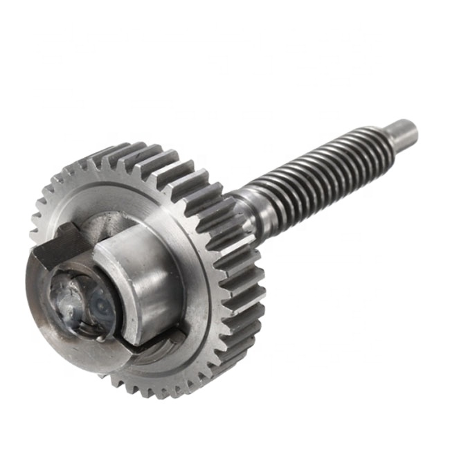
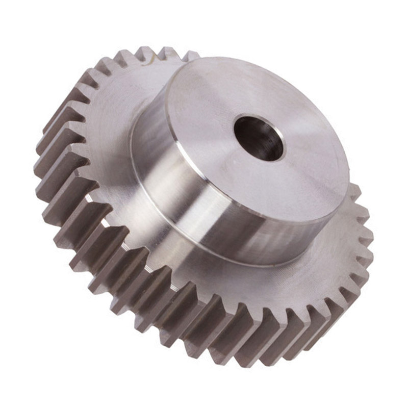
Straight cut gears, also known as spur gears, are the simplest and most common type of cylindrical gears. They are characterized by teeth that are cut straight and parallel to the gear's axis of rotation. This straightforward tooth orientation gives them their name "straight cut." Each tooth is a segment of a straight line running the entire width of the gear, and they are evenly spaced around the circumference, forming a circular pattern.
The basic components of a straight cut gear include the pitch circle (an imaginary circle where meshing gears make contact), the addendum (the part of the tooth above the pitch circle), the dedendum (the part below the pitch circle), the tooth face, and the tooth flank. The number of teeth on a gear determines its size and its role in speed and torque conversion within a gear system.
How They Mesh and Transmit Motion
Straight cut gears operate by meshing with another gear (or a gear rack in some cases) such that the teeth of one gear fit into the spaces between the teeth of the other. When two straight cut gears are in mesh, the driving gear (input gear) transfers its rotational motion to the driven gear (output gear). The contact between the teeth is along a straight line that is parallel to the gear axes, resulting in a pure rolling motion at the point of contact (the pitch circle), with some sliding motion occurring along the tooth flanks.
One key characteristic of straight cut gear meshing is that they produce a direction change in the rotational motion: if the driving gear rotates clockwise, the driven gear will rotate counterclockwise, and vice versa. This makes them suitable for applications where a direction reversal is needed.
Design Characteristics of Straight Cut Gears
Tooth Geometry and Parameters
- Module or Diametral Pitch: These are measures of the gear's tooth size. Module (m) is the ratio of the pitch diameter to the number of teeth (m = d/z), while diametral pitch (DP) is the number of teeth per inch of pitch diameter (DP = z/d). Both parameters define the gear's size and tooth spacing.
- Pressure Angle: The pressure angle is the angle between the line of action (the line along which force is transmitted between meshing teeth) and the tangent to the pitch circle. Common pressure angles are 20° and 14.5°, with 20° being the standard in modern applications. A larger pressure angle provides stronger teeth but increases the radial force between meshing gears.
- Face Width: This is the width of the gear along its axis. A wider face width can distribute load more evenly but increases the gear's weight and size.
Material Options
Straight cut gears can be made from a variety of materials depending on the application requirements:
- Steels: Carbon steel and alloy steel are popular for their strength and durability. Heat treatment processes like carburizing, quenching, and tempering are often used to enhance surface hardness and core toughness.
- Plastics: Nylon and polycarbonate are used in low-load, low-speed applications where noise reduction and cost are important, such as in consumer electronics and office equipment.
- Metals: Aluminum and brass are used for lightweight or corrosion-resistant applications, though they have lower load-carrying capacity compared to steel.
- Composite Materials: In some specialized cases, composite materials are used to achieve a balance of strength, weight, and chemical resistance.
Manufacturing Processes
The simplicity of straight cut gear design makes them relatively easy and cost-effective to manufacture compared to other gear types like helical or bevel gears. Common manufacturing methods include:
- Hobbing: A hobbing machine uses a cutting tool (hob) that mimics the shape of the gear teeth to cut the teeth into the blank in a rotational process. This is efficient for producing gears in bulk.
- Shaping: A gear shaper uses a reciprocating cutting tool to form the teeth, suitable for smaller production runs or internal gears.
- Broaching: Used for cutting internal gears or gears with specific tooth profiles, though it is less common for straight cut gears.
- Casting and Forging: For larger gears or when specific material properties are needed, casting (for complex shapes) or forging (for enhanced strength) may be used, followed by machining to finish the teeth.
How Straight Cut Gears Work: The Mechanics of Motion Transfer
Gear Ratio Calculation
The gear ratio (GR) in a straight cut gear system is determined by the number of teeth on the driving gear (N1) and the driven gear (N2). The ratio can be calculated as:
If the driving gear has fewer teeth than the driven gear (N1 < N2), the system provides a speed reduction (output speed < input speed) and a torque increase, following the principle that torque is inversely proportional to speed when power is constant (assuming 100% efficiency). Conversely, if the driving gear has more teeth (N1 > N2), the system acts as a speed multiplier, increasing output speed while decreasing torque.
Force and Load Distribution
When straight cut gears mesh, the contact between teeth creates both tangential and radial forces. The tangential force (Ft) is responsible for transmitting torque and is calculated as:
where T is the torque and d is the pitch diameter. The radial force (Fr) acts along the line of the gear axis and is a result of the pressure angle:
where α is the pressure angle. This radial force must be supported by the gearshaft bearings, which is an important consideration in the mechanical design of the system.
Due to the straight tooth orientation, the contact between teeth occurs along the entire face width simultaneously when the teeth engage. This can lead to sudden loading and unloading of the teeth, contributing to the characteristic noise and vibration associated with straight cut gears, especially at higher speeds.
Applications of Straight Cut Gears
Industrial Machinery
Straight cut gears are widely used in various industrial applications where simplicity, durability, and high torque transmission are required:
- Conveyor Systems: In belt conveyors and roller conveyors, straight cut gears drive the pulleys or rollers, ensuring reliable motion transfer even under heavy loads.
- Gearboxes for Industrial Equipment: Many industrial gearboxes, such as those in pumps, compressors, and mixers, utilize straight cut gears for their straightforward design and ease of maintenance.
- Machine Tools: Lathes, milling machines, and drilling machines often use straight cut gears in their feed mechanisms and spindle drives to achieve precise speed and torque control.
Automotive Applications
While helical gears are more common in modern automotive transmissions for their quieter operation, straight cut gears still have specific uses:
- Manual Transmissions (Dog Engagement Gears): In some racing cars and heavy-duty trucks, straight cut gears are used in manual transmissions for their high strength and ability to handle sudden torque spikes. The "notchy" feel of shifting is a result of their design.
- Transfer Cases: In four-wheel-drive vehicles, transfer cases may use straight cut gears to distribute power to the front and rear axles, especially in off-road vehicles where robust gear performance is critical.
- Engine Accessories: Components like oil pumps and coolant pumps in engines often use small straight cut gears due to their simplicity and cost-effectiveness.
Agricultural Machinery
The harsh operating conditions in agriculture demand gears that are durable and easy to maintain:
- Tractors: Straight cut gears are used in the transmission systems of tractors, particularly in older models or specialized agricultural equipment, to handle the high torque required for plowing, tilling, and hauling.
- Harvesting Equipment: Combines and harvesters use straight cut gears in their cutting, threshing, and conveying mechanisms, where reliability and the ability to withstand debris are essential.
Gear Pumps and Fluid Systems
Straight cut gears are a key component in external gear pumps, which are used to transfer fluids:
- Hydraulic Systems: Gear pumps with straight cut gears provide a consistent flow rate and are commonly used in hydraulic power units for industrial machinery, construction equipment, and aircraft systems.
- Oil Circulation Systems: In engines and industrial machinery, straight cut gears in oil pumps ensure proper lubrication by circulating oil under pressure.
Consumer and Office Equipment
In less demanding applications where cost and simplicity matter:
- Clock Mechanisms: Clocks and watches use small straight cut gears to transfer motion from the mainspring or motor to the hands, taking advantage of their ease of manufacture.
- Printer and Scanner Mechanisms: The paper feed systems in printers and scanners often employ plastic straight cut gears to minimize noise and cost while providing reliable motion.
Advantages of Straight Cut Gears
Simplicity and Cost-Effectiveness
The straight tooth design is the simplest among all gear types, making straight cut gears easier to design, manufacture, and inspect. This simplicity reduces production costs, especially for large quantities, and lowers the barrier to entry for both manufacturers and users.
High Efficiency
Due to their minimal sliding motion at the pitch circle and straightforward tooth engagement, straight cut gears offer high mechanical efficiency, often exceeding 90% in well-lubricated systems. This efficiency is crucial in applications where energy conservation is important.
High Torque Capacity
When made from strong materials like heat-treated steel, straight cut gears can handle high torque loads effectively. The direct contact between teeth along the entire face width distributes the load relatively evenly, making them suitable for heavy-duty applications.
Easy Maintenance and Repair
Their simple design means that straight cut gears are easier to install, align, and replace compared to more complex gear types. In many cases, individual gears can be replaced without needing to overhaul the entire gear system.
Disadvantages of Straight Cut Gears
Noise and Vibration
The most significant drawback of straight cut gears is their noisy operation, especially at higher speeds. As the teeth engage abruptly (contact occurs along the entire face width at once), they generate impact forces that lead to noise and vibration. This is in contrast to helical gears, where teeth engage gradually, reducing impact.
Limited Speed Range
Due to the noise and vibration issues, straight cut gears are generally not recommended for high-speed applications. The sudden loading and unloading of teeth can cause resonance and excessive wear at higher rotational speeds, limiting their use to moderate or low-speed systems.
Radial Load on Bearings
The pressure angle in straight cut gears creates a radial force that acts on the shaft bearings, as discussed earlier. This requires the use of stronger bearings and may increase the overall size and weight of the gear system, especially in high-torque applications.
Potential for Early Wear
The sliding motion along the tooth flanks, combined with the impact forces during engagement, can lead to faster wear compared to gears with more gradual tooth engagement, such as helical gears. Proper lubrication is critical to mitigate this issue, but it doesn't eliminate it entirely in high-speed or poorly maintained systems.
Straight Cut Gears vs. Other Gear Types
Straight Cut Gears vs. Helical Gears
- Tooth Design: Straight cut gears have straight teeth, while helical gears have angled (helical) teeth.
- Meshing Behavior: Straight cut teeth engage suddenly, causing noise; helical teeth engage gradually, resulting in smoother and quieter operation.
- Load Distribution: Helical gears distribute load over multiple teeth due to their angled teeth, allowing higher load capacity at higher speeds. Straight cut gears have single-tooth contact along the face width at any instant (in theory, though in practice, multiple teeth may be in contact depending on face width and backlash).
- Axial Thrust: Helical gears generate axial thrust due to their helical angle, requiring thrust bearings; straight cut gears have only radial thrust, simplifying bearing design.
Straight Cut Gears vs. Bevel Gears
- Application: Straight cut gears are used for parallel shafts, while bevel gears are used for intersecting shafts (typically at 90°).
- Tooth Design: Bevel gears have conical shapes with teeth that can be straight (straight bevel gears) or curved (spiral bevel gears). Straight bevel gears share some noise characteristics with straight cut gears, while spiral bevel gears are quieter like helical gears.
- Manufacturing Complexity: Bevel gears are more complex to manufacture and require precise alignment, making them more expensive than straight cut gears for parallel shaft applications.
Straight Cut Gears vs. Worm Gears
- Speed Ratio: Worm gears can achieve very high gear ratios (e.g., 50:1) in a compact space, while straight cut gears are typically used for lower ratios (up to around 10:1 in a single stage).
- Efficiency: Worm gears have lower efficiency due to the sliding contact between the worm and the gear, while straight cut gears have higher efficiency.
- Self-Locking: Worm gears can be self-locking (preventing backdriving), which is useful in certain applications, while straight cut gears are not self-locking.
Maintenance and Lubrication of Straight Cut Gears
Lubrication Best Practices
Proper lubrication is essential to reduce wear, noise, and heat generation in straight cut gear systems:
- Lubricant Type: Use oils with appropriate viscosity (based on speed and load) for most industrial applications. Greases may be used in slow-speed or open gear systems.
- Lubrication Methods: Circulating oil systems are ideal for high-load, high-speed applications to provide continuous cooling and lubrication. For low-speed or occasional-use systems, manual lubrication with grease or oil may suffice.
- Lubrication Frequency: Follow manufacturer guidelines, but generally, inspect lubricant levels and condition regularly. High-temperature or high-dust environments may require more frequent changes.
Alignment and Clearance Checks
- Parallelism: Ensure that the shafts are perfectly parallel to prevent uneven tooth loading, which can cause premature wear or tooth breakage.
- Backlash Adjustment: Backlash (the play between meshing teeth) should be adjusted according to the application requirements. Too much backlash causes noise and vibration; too little can lead to binding and overheating.
Material Selection for Longevity
- Choose materials that match the application's load, speed, and environmental conditions. For example, use heat-treated steel for high-torque industrial gearboxes and plastic gears for low-load consumer devices.
- Consider surface coatings or treatments, such as shot peening or nitriding, to enhance surface hardness and wear resistance.
Regular Inspections
- Visually inspect gears for signs of wear, such as pitting, scoring, or broken teeth.
- Monitor operating temperatures and noise levels; sudden increases may indicate lubrication issues, misalignment, or excessive load.
Conclusion: The Role of Straight Cut Gears in Mechanical Systems
Straight cut gears may lack the smoothness and high-speed capabilities of helical gears or the compactness of worm gears, but their simplicity, cost-effectiveness, and high torque capacity make them indispensable in a wide range of applications. From industrial machinery and automotive transmissions to agricultural equipment and consumer devices, they serve as a reliable foundation for motion and power transfer in systems where durability and straightforward design are prioritized.
Understanding their design characteristics, advantages, and limitations allows engineers and designers to make informed decisions about when to use straight cut gears and how to optimize their performance through proper material selection, lubrication, and maintenance. As with any mechanical component, their effectiveness lies in matching their capabilities to the specific needs of the application, ensuring reliable and efficient operation for years to come.
Whether you're designing a new gear system or maintaining an existing one, straight cut gears remain a timeless choice, proving that sometimes simplicity is the key to mechanical excellence.
How Automatic Gear Transmission Works
How to Adjust Front Derailleur Gears
Related Article

Gears are the backbone of mechanical transmission systems, converting rotational motion and torque between shafts to power everything from household appliances to industrial machinery.
What are the 4 types of gears

CNC machines (Computer Numerical Control machines) have transformed manufacturing by delivering unmatched precision, repeatability, and efficiency across material types—from metals to plastics and composites.
Which Industries Mostly Use CNC Machines

CNC machining is celebrated for its precision and versatility in shaping metals, plastics, and composites—but its subtractive nature (removing material from a solid workpiece to create parts) raises a critical question: “Is CNC machining wasteful?” At first glance, the piles of metal shavings, plastic chips, and scrapped parts from CNC operations might suggest yes.
Is CNC machining wasteful
