
How to Calculate Gear Ratio
2025-06-25
How to Calculate Gear Ratio?
In mechanical engineering, the gear ratio is a fundamental concept that determines how speed and torque are transferred between meshing gears. Whether you’re designing a robotic arm, troubleshooting a car transmission, or building a DIY machine, understanding how to calculate gear ratio is essential for optimizing performance. This blog post will break down the basics of gear ratio, explain the key formulas, and guide you through calculations for different gear types and systems.
What Is a Gear Ratio? The Core Concept
The gear ratio represents the relationship between the number of teeth, speed, or torque of two meshing gears. It describes how many times the driving gear (input gear) must rotate to make the driven gear (output gear) rotate once. A gear ratio of N:1 means the driven gear rotates once for every N rotations of the driving gear.
Key Relationships
- Speed: Gear ratio inversely affects rotational speed:
Driven Gear Speed = Driving Gear Speed ÷ Gear Ratio
- Torque: Gear ratio directly affects torque:
Driven Gear Torque = Driving Gear Torque × Gear Ratio
- Teeth Count: The ratio is determined by the number of teeth on each gear, making it a key design parameter for mechanical systems.
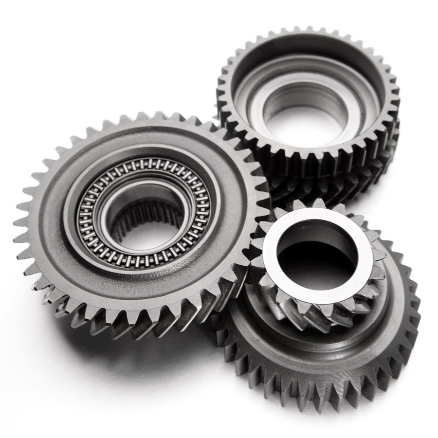
Step-by-Step Guide to Calculating Gear Ratio
1. Basic Calculation for Spur Gears
Spur gears (the most common type with straight teeth on parallel shafts) use a simple formula based on tooth count:
Formula:
Gear Ratio (GR) = Number of Teeth on Driven Gear (N₂) ÷ Number of Teeth on Driving Gear (N₁)
Example:
If a driving gear has 20 teeth and a driven gear has 60 teeth:
GR = 60 ÷ 20 = 3:1
Meaning: The driven gear rotates 1 time for every 3 rotations of the driving gear (speed is reduced by 1/3, torque is tripled).
2. Using Speed or RPM
When speed (RPM, revolutions per minute) is known instead of teeth count, the formula reverses (since speed is inversely proportional to teeth count):
Formula:
Gear Ratio (GR) = Driving Gear Speed (RPM₁) ÷ Driven Gear Speed (RPM₂)
Example:
If a motor drives a gear at 1200 RPM, and the meshing gear spins at 400 RPM:
GR = 1200 ÷ 400 = 3:1
(Same result as the teeth-based calculation, confirming the inverse relationship between teeth and speed.)
3. Calculating Torque Ratio
Since torque is directly proportional to the gear ratio (assuming 100% efficiency), use:
Formula:
Torque Ratio = Gear Ratio = Driven Gear Torque (T₂) ÷ Driving Gear Torque (T₁)
Example:
A motor provides 5 Nm of torque to a 20-tooth gear meshing with a 60-tooth gear:
T₂ = 5 Nm × 3 = 15 Nm
(The driven gear outputs 3 times the input torque.)
Gear Ratio Calculations for Different Gear Types
While the basic tooth-count formula applies to most gear types, here’s how it adapts to specialized gears:
1. Helical Gears
- Same formula as spur gears (teeth count ratio), as helical teeth (angled teeth) don’t affect the basic speed/torque relationship—only noise, load capacity, and axial forces.
2. Bevel Gears
- Used for intersecting shafts (e.g., 90° angles in car differentials).
- Formula remains GR = N₂ ÷ N₁, but ensure gears are properly aligned and have matching cone angles.
3. Worm Gears
- Composed of a worm (screw-like gear) and a worm wheel.
- GR = Number of Wheel Teeth ÷ Number of Worm Threads (most worms have 1-4 threads).
Example: A worm with 1 thread and a 40-tooth wheel has GR = 40:1.
4. Compound Gear Systems (Multiple Stages)
- For systems with multiple gear pairs (e.g., a 3-stage gearbox):
-
- Calculate the ratio for each stage (GR₁, GR₂, GR₃).
-
- Multiply all stage ratios for the total gear ratio:
Total GR = GR₁ × GR₂ × GR₃
Example: Stage 1 (2:1) + Stage 2 (3:1) = Total GR = 2 × 3 = 6:1.
Practical Applications and Examples
1. Bicycle Gear System
- Front chainring (driving gear): 52 teeth
- Rear cog (driven gear): 13 teeth
- Gear Ratio = 52 ÷ 13 = 4:1
- Meaning: The rear wheel rotates 1 time for every 4 rotations of the pedals (high speed, low torque for flat terrain).
2. Car Transmission
- In first gear, a small pinion gear (15 teeth) drives a large ring gear (60 teeth):
GR = 60 ÷ 15 = 4:1
- This high ratio provides high torque for accelerating from rest, sacrificing speed.
3. Robotics
- A robotic arm uses a worm gear with 1 thread and a 50-tooth wheel:
GR = 50:1
- The slow, high-torque output ensures precise and stable movement of heavy payloads.
Common Questions and Pitfalls
1. What If Gears Have Different Pitch Diameters?
- Pitch diameter (the “effective” diameter where teeth mesh) is proportional to teeth count (for gears with the same pitch), so the teeth-count formula still holds.
2. How Does Gear Efficiency Affect Torque?
- Real-world gears lose energy to friction (e.g., helical gears ~98% efficient, worm gears ~70-85%).
- Adjust torque calculations with an efficiency factor (η):
Driven Torque = Input Torque × GR × η
3. Can Gear Ratio Be Less Than 1?
- Yes! A ratio <1 (e.g., 0.5:1) means the driven gear spins faster than the driving gear (used for speed increase, the torque decreases).
Example: 10-tooth driving gear + 5-tooth driven gear = GR = 5 ÷ 10 = 0.5:1.
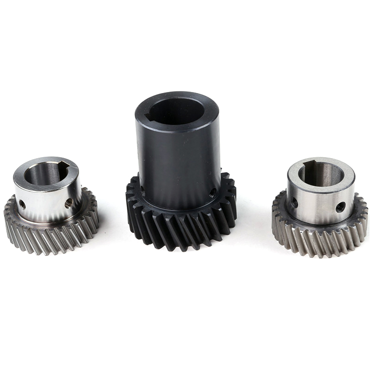
Visual Aids: Illustrating Gear Structures
While actual images can’t be embedded here, consider these diagrams in your content:
- Spur Gear Meshing: Show two parallel gears with labeled teeth counts and arrows indicating rotation direction.
- Worm Gear System: Depict a worm (screw) meshing with a wheel, highlighting the single thread vs. wheel teeth.
- Compound Gear Train: Illustrate multiple gear pairs with stages labeled, showing how ratios multiply.
Conclusion: Mastering Gear Ratio for Mechanical Design
Calculating gear ratio is a foundational skill for anyone working with mechanical systems. Whether you’re optimizing speed, maximizing torque, or designing complex gear trains, the core formula—driven teeth ÷ driving teeth—serves as your starting point. By adapting this to different gear types and multi-stage systems, you can unlock precise control over motion and power in applications ranging from bicycles to industrial machinery.
Remember: Gear ratio is more than a number—it’s the bridge between input and output, enabling engineers and hobbyists alike to transform raw motion into purposeful mechanical action. With practice, you’ll effortlessly apply these calculations to solve real-world engineering challenges.
What Is a Pinion Gear
What Is a Gear
Related Article

Gears are the backbone of mechanical transmission systems, converting rotational motion and torque between shafts to power everything from household appliances to industrial machinery.
What are the 4 types of gears

CNC machines (Computer Numerical Control machines) have transformed manufacturing by delivering unmatched precision, repeatability, and efficiency across material types—from metals to plastics and composites.
Which Industries Mostly Use CNC Machines

CNC machining is celebrated for its precision and versatility in shaping metals, plastics, and composites—but its subtractive nature (removing material from a solid workpiece to create parts) raises a critical question: “Is CNC machining wasteful?” At first glance, the piles of metal shavings, plastic chips, and scrapped parts from CNC operations might suggest yes.
Is CNC machining wasteful
