
How Do Gears Work
2025-07-04
How Do Gears Work?
Gears are among the most fundamental and versatile components in mechanical engineering, driving everything from simple wristwatches to massive industrial machines. But have you ever wondered how these toothed wheels actually work? Despite their common presence, the mechanics behind gear operation involve precise geometry, mechanical principles, and engineering design. In this article, we’ll unravel the mysteries of gears—exploring their core working principles, different types, and how they transmit motion and power in various applications. Whether you’re a student, DIY enthusiast, or engineer, understanding how gears work is essential for appreciating their role in modern machinery.
Understanding the Basics of Gears: What They Are and How They Function
What Is a Gear?
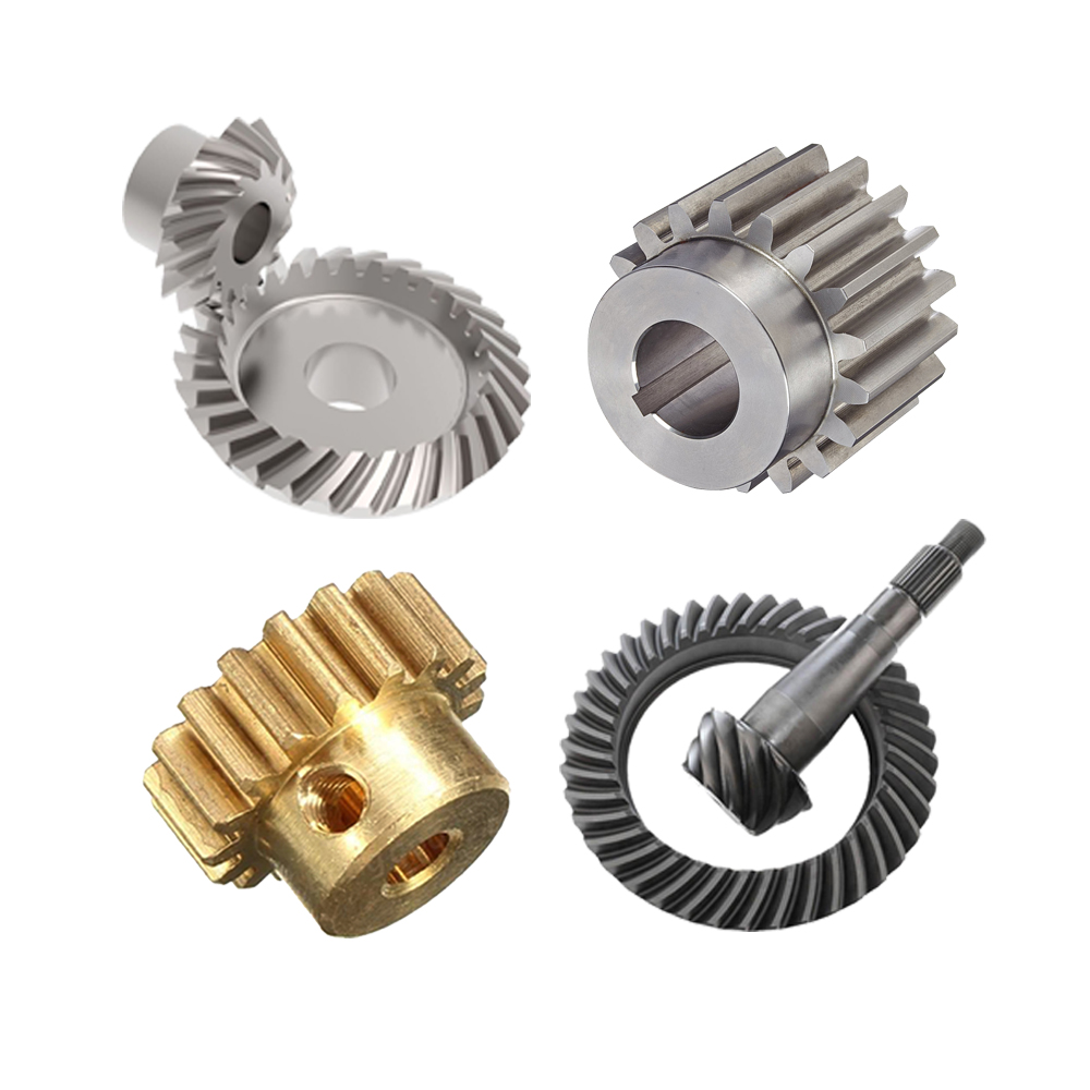
A gear is a rotating machine part with cut teeth (or cogs) that mesh with another toothed part to transmit torque and rotational motion. Unlike friction-based drives like belts or chains, gears rely on direct contact between teeth, making them highly efficient and precise for power transmission. The basic components of a gear include:
- Teeth: The protruding parts around the circumference, designed to interlock with teeth on another gear.
- Pitch Circle: An imaginary circle that defines the effective radius of the gear, where the teeth are centered.
- Module (or Diametral Pitch): A measure of tooth size, defined as the ratio of pitch diameter to the number of teeth (common in metric systems) or the inverse in imperial systems.
The Core Principle: Meshing and Motion Transfer
Gears work through meshing—the process where the teeth of one gear engage with the teeth of another. When two gears mesh:
- Force Transmission: A driving gear (input gear) transfers rotational force to a driven gear (output gear) through tooth contact.
- Direction Change: Meshing gears reverse the direction of rotation (e.g., a clockwise rotating gear will make a meshed adjacent gear rotate counterclockwise).
- Speed and Torque Conversion: The ratio of teeth between gears determines how speed and torque change. A gear with fewer teeth (pinion) driving a gear with more teeth (gear) will reduce speed but increase torque, and vice versa.
The Fundamental Mechanics of Gear Operation
Gear Ratio: The Key to Speed and Torque Adjustment
The gear ratio (GR) is the ratio of the number of teeth on the driven gear to the number of teeth on the driving gear:
GR = Number of Teeth on Driven Gear / Number of Teeth on Driving Gear
This ratio directly affects rotational speed and torque:
- Speed Relationship: Output Speed (RPM) = Input Speed (RPM) / GR
(e.g., a 2:1 gear ratio halves the output speed).
- Torque Relationship: Output Torque = Input Torque × GR
(e.g., a 2:1 ratio doubles the output torque).
This principle is why gears are critical in devices like car transmissions—they allow adjusting speed and torque to match the task (e.g., high torque for climbing hills or high speed for cruising).
The Geometry of Meshing: How Teeth Stay Engaged
For gears to mesh smoothly, their teeth must have compatible shapes. The most common tooth profile is the involute curve, which ensures a constant gear ratio as the gears rotate. Key geometric considerations include:
- Pressure Angle: The angle between the line of contact between teeth and the line tangent to the pitch circles, typically 20° in modern gears, which balances strength and efficiency.
- Clearance: The small space between the tip of a tooth and the root of the meshing tooth, preventing binding while allowing lubrication.
Types of Gears and Their Unique Operations
Gears come in various shapes and sizes, each designed for specific motion transfer needs. Let’s explore the main types and how they work:
1. Spur Gears: Straight Teeth for Parallel Shafts
- Structure: The simplest type of gear,with straight teeth parallel to the shaft axis.
- Operation: Mesh with other spur gears on parallel shafts, transmitting motion at a 1:1 direction reversal (if same size) or with speed/torque changes (if different sizes).
- Pros: Simple design, low cost, high efficiency (up to 90-95%).
- Cons: Noisy at high speeds due to sudden tooth engagement.
- Applications: Lawnmowers, washing machines, simple gearboxes.
2. Helical Gears: Angled Teeth for Smooth Operation
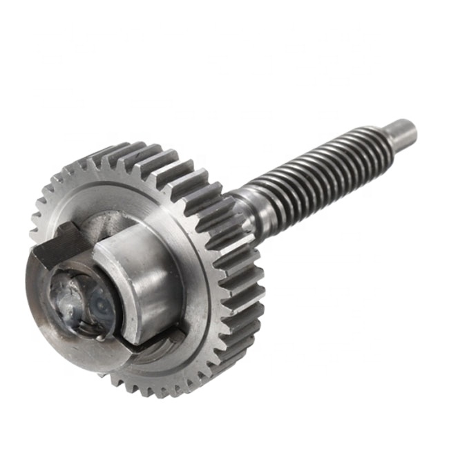
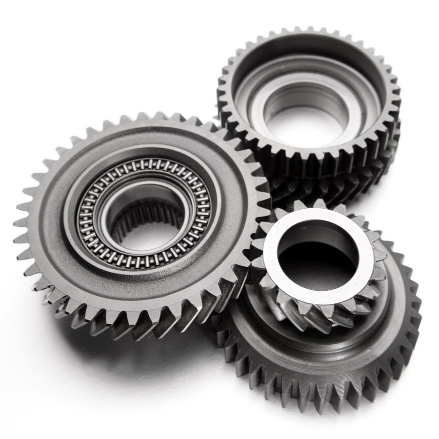
- Structure: Teeth are cut at an angle (helix angle) to the shaft axis, often in left or right hand.
- Operation: As the angled teeth mesh gradually, they reduce impact and noise compared to spur gears. Two helical gears on parallel shafts can also transmit motion, but a pair of helical gears with opposite hand can connect crossed shafts (called "crossed helical gears").
- Pros: Quieter, smoother operation; capable of handling higher loads.
- Cons: Generate axial thrust, requiring thrust bearings; slightly lower efficiency (85-90%) due to sliding friction.
- Applications: Car transmissions, industrial gearboxes, printers.
3. Bevel Gears: Conical Shape for Angular Shafts
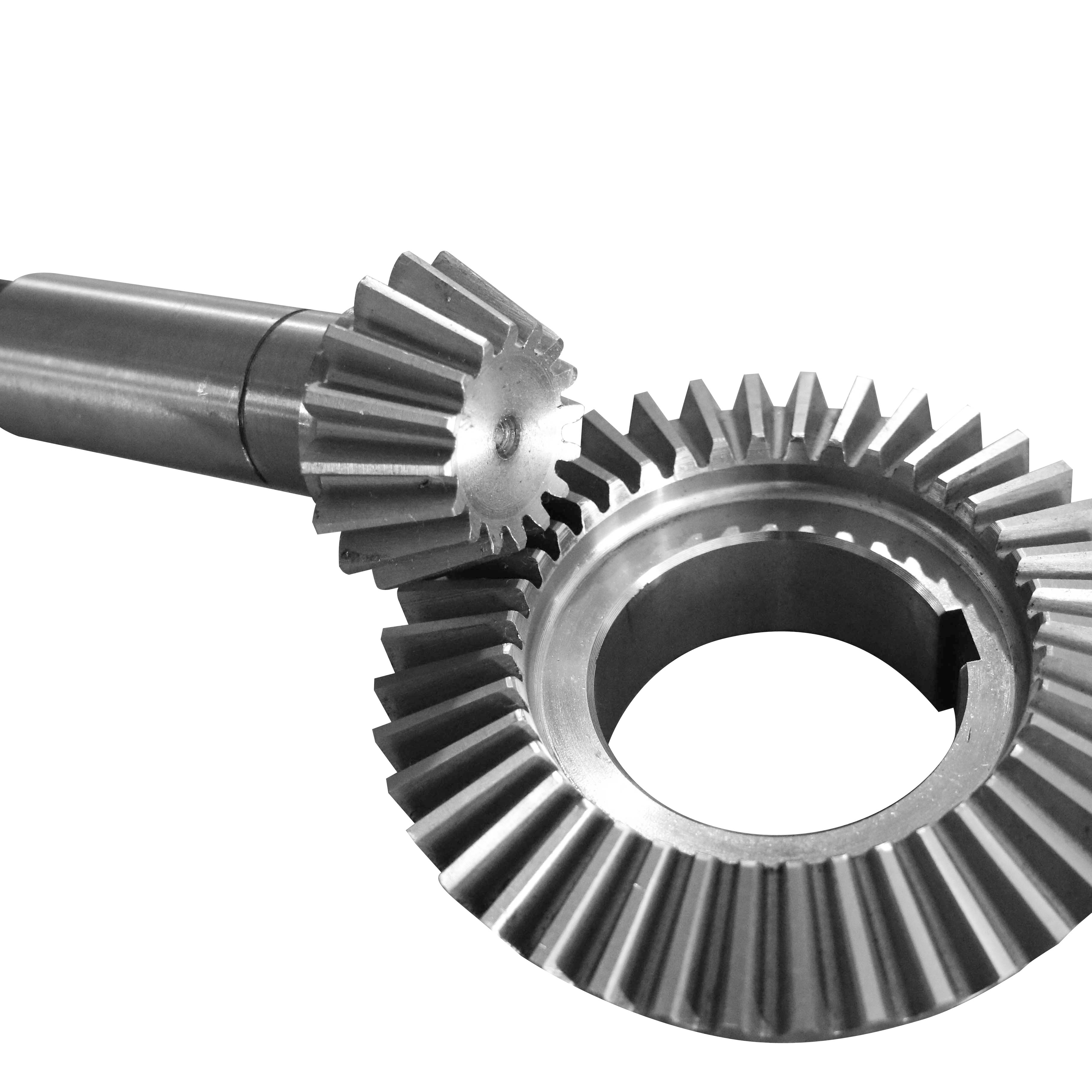
- Structure: Bevel gear,used to connect shafts intersecting at an angle (typically 90°).
- Types:
-
- Straight Bevel Gears: Simple straight teeth, noisy at high speeds.
-
- Spiral Bevel Gears: Curved, angled teeth for gradual meshing, similar to helical gears but on cones.
-
- Zerol Bevel Gears: Curved teeth with zero helix angle, a compromise between straight and spiral.
- Operation: Transmit motion between intersecting shafts, changing both direction and speed/torque.
- Pros: Compact, suitable for right-angle drives.
- Cons: Complex manufacturing; spiral types require precise alignment.
- Applications: Car differentials, power tools, aviation systems.
4. Worm Gears: Screw-like for High Gear Ratios
- Structure: Consists of a worm (a screw-like gear) and a worm gear (a gear with helical teeth).
- Operation: The worm drives the worm gear, providing a high gear ratio (e.g., 10:1 to 50:1) in a compact space. The worm’s single or multiple threads (like a screw’s pitch) determine the ratio.
- Key Feature: Most worm gear systems are self-locking—the worm can drive the gear, but the gear cannot drive the worm (due to low lead angle), making them ideal for holding positions (e.g., elevators).
- Pros: High torque multiplication, quiet operation, compact.
- Cons: Low efficiency (as low as 50-60%) due to sliding friction; requires heavy lubrication.
- Applications: Elevators, conveyor belts, steering systems, 3D printer lead screws.
5. Rack and Pinion: Converting Rotation to Linear Motion
- Structure: A pinion gear (small cylindrical gear) meshes with a rack (a straight, toothed bar).
- Operation: Rotating the pinion causes the rack to move linearly, and vice versa.
- Pros: Smooth, precise linear motion; used where linear actuation is needed.
- Cons: Limited travel distance (length of the rack); requires support to prevent bending.
- Applications: Car steering systems, CNC machines, linear actuators, printers.
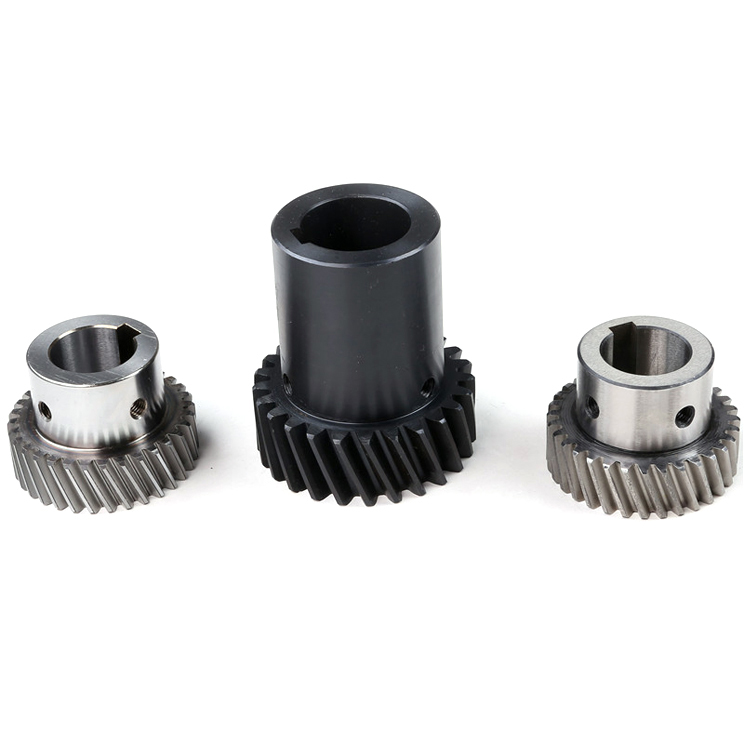
6. Herringbone Gears: Double Helical for High Loads
- Structure: Two mirrored helical gears side by side, forming a "V" shape (like a herringbone pattern), eliminating axial thrust.
- Operation: Combines the smoothness of helical gears with no net axial force (since the left and right helical angles cancel each other’s thrust).
- Pros: High load capacity, quiet, suitable for high-speed applications.
- Cons: Complex and expensive to manufacture; thicker than single helical gears.
- Applications: Heavy machinery, marine transmissions, industrial gearboxes.
How Gears Work in Real-World Applications
1. Car Transmissions: Adjusting Speed and Torque for Performance
In a manual transmission:
- Low Gear (High GR): A small pinion drives a large gear, providing high torque for starting or climbing—trading speed for power.
- High Gear (Low GR): A large pinion drives a small gear, allowing the engine to run at lower RPM for highway speed, improving efficiency.
The gearshift selects different gear pairs to change the gear ratio, optimizing performance for driving conditions.
2. Bicycles: Simple Gear Systems for Pedaling Efficiency
- Front Chainrings and Rear Cogs: A small front chainring with a large rear cog (low gear) makes pedaling easier uphill (high torque, low speed). A large front chainring with a small rear cog (high gear) allows fast pedaling on flat terrain (low torque, high speed).
- Derailleurs: Shift the chain between different cogs to change the effective gear ratio, demonstrating the core principle of speed/torque trade-off.
3. Clocks and Watches: Precise Motion Control
- Gear Trains: A series of gears with specific tooth counts ensure the minute, hour, and second hands move at the correct rates. For example, a 60-tooth gear driven by a 1-tooth pinion (from a balance wheel) creates the 60:1 ratio needed for seconds to minutes.
- Precision Meshing: Involute teeth and careful lubrication ensure minimal backlash (play between teeth), critical for timekeeping accuracy.
4. Industrial Machinery: Heavy-Duty Power Transmission
In manufacturing plants:
- Helical or Herringbone Gears: Handle high loads in conveyor systems, reducing noise and wear.
- Worm Gears: Used in lifts and hoists for self-locking safety, preventing accidental movement when power is cut.
- Rack and Pinion: Enable precise linear motion in robotic arms or CNC routers, translating motor rotation to accurate positioning.
Key Considerations in Gear Design and Operation
1. Backlash: The Enemy of Precision
Backlash is the play between meshing teeth, causing a delay in motion transfer and potential vibration. It’s minimized in precision applications (e.g., robotics) through:
- Closer tooth tolerances
- Anti-backlash gear designs (e.g., split gears with spring-loaded halves)
- Proper lubrication to reduce wear-induced backlash.
2. Lubrication: Essential for Longevity
Gears rely on lubricants to:
- Reduce friction and wear between teeth
- Cool the gears by dissipating heat
- Prevent corrosion and debris accumulation
Common lubricants include oils (for high-speed gears) and greases (for slow-moving, heavy-load gears).
3. Material Selection: Matching Strength and Environment
Gears are made from materials like:
- Steel: High strength for heavy loads (e.g., car transmissions).
- Aluminum or Plastic: Lightweight and quiet, used in consumer devices (e.g., printers, toys).
- Brass or Bronze: Low friction, ideal for worm gears or marine applications.
Heat treatment (e.g., carburizing, quenching) is often used to harden tooth surfaces and improve durability.
Conclusion: The Indispensable Role of Gears in Mechanical Systems
Gears are far more than just "toothed wheels"—they’re precision-engineered components that leverage geometric principles to transform motion and power in infinitely adaptable ways. From the simple spur gears in a child’s toy to the complex helical systems in industrial turbines, their core working principle remains the same: meshing teeth to transmit torque with controlled speed, direction, and force.
Understanding how gears work means appreciating the balance between engineering design (tooth profile, material, type) and mechanical needs (torque, speed, efficiency). Whether you’re troubleshooting a noisy gearbox, designing a robotic arm, or simply curious about the mechanics of everyday devices, this knowledge empowers you to make informed decisions about gear selection and maintenance.
As technology advances, gears continue to evolve—with 3D-printed plastic gears for prototyping, nanogears in microdevices, and advanced coatings for extreme environments. Yet their fundamental role as the backbone of mechanical transmission remains unchanged. By mastering the basics of gear mechanics, you gain a foundational understanding of how the mechanical world around you operates—one tooth at a time.
How Does a Differential Gear Work
How Automatic Gear Transmission Works
Related Article

Gears are the backbone of mechanical transmission systems, converting rotational motion and torque between shafts to power everything from household appliances to industrial machinery.
What are the 4 types of gears

CNC machines (Computer Numerical Control machines) have transformed manufacturing by delivering unmatched precision, repeatability, and efficiency across material types—from metals to plastics and composites.
Which Industries Mostly Use CNC Machines

CNC machining is celebrated for its precision and versatility in shaping metals, plastics, and composites—but its subtractive nature (removing material from a solid workpiece to create parts) raises a critical question: “Is CNC machining wasteful?” At first glance, the piles of metal shavings, plastic chips, and scrapped parts from CNC operations might suggest yes.
Is CNC machining wasteful
